Handle arm mounting structure for fishing reel

Active Publication Date: 2010-09-30
SHIMANO INC
View PDF12 Cites 13 Cited by
  • Summary
  • Abstract
  • Description
  • Claims
  • Application Information

AI Technical Summary

Benefits of technology

[0008]One object of the present invention is to provide a handle arm mounting stru

Problems solved by technology

In the conventional handle arm mounting structure mentioned above, the non-circular section of the handle shaft can be formed with good precision using a machining method, but it is difficult to machine the non-c

Method used


Image

  • Handle arm mounting structure for fishing reel
  • Handle arm mounting structure for fishing reel
  • Handle arm mounting structure for fishing reel

Examples


second embodiment

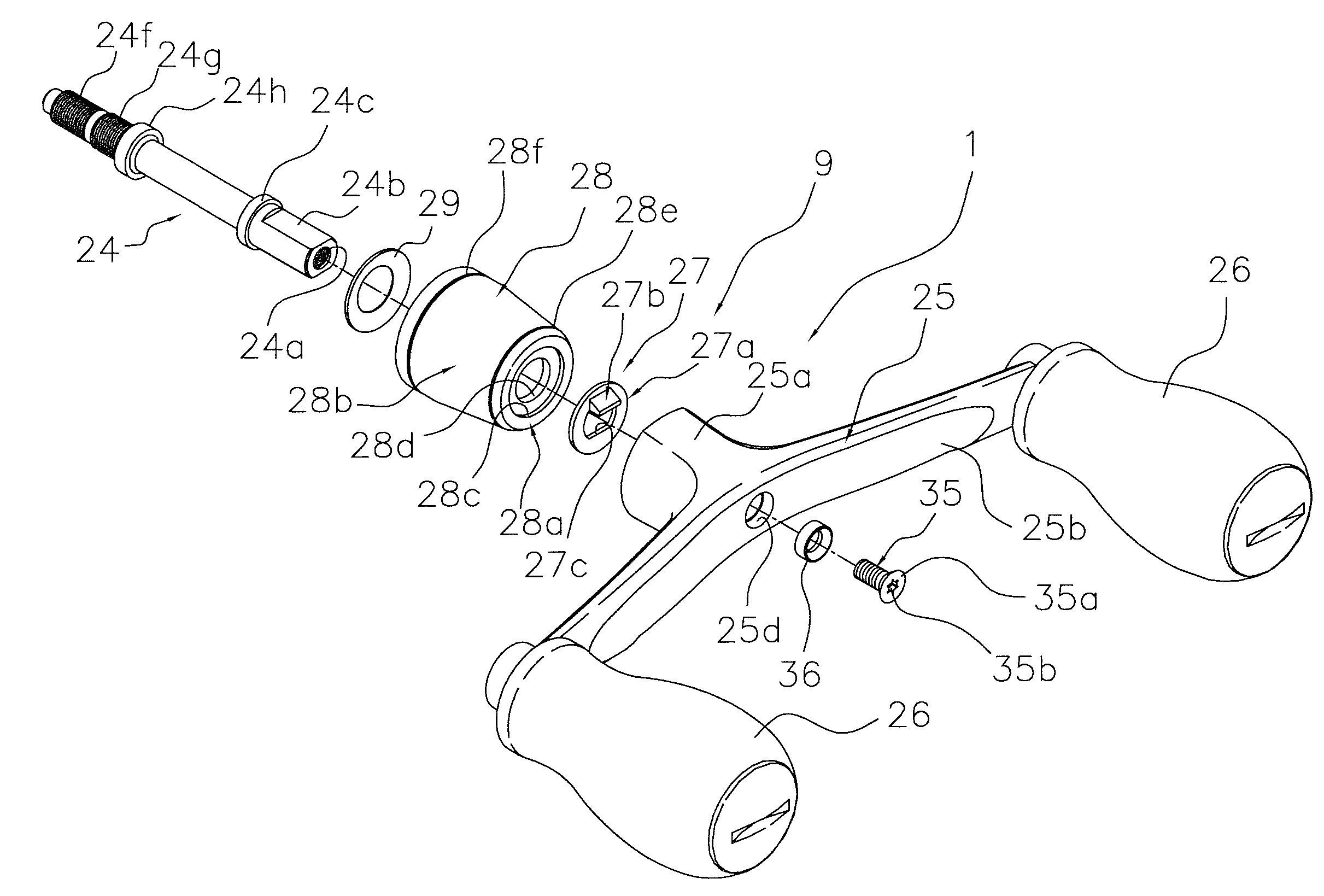
[0063]While in the first embodiment the engaging protrusion 27b of the washer member 27 is provided on a portion corresponding to one of the third line segments 27g, in the second embodiment engaging protrusions 127b are provided on a portion corresponding to the second circular arcs 127h, as shown in FIGS. 8 to 11. The second embodiment will now be explained chiefly in terms of its differences with respect to the first embodiment. Parts of the second embodiment that are the same as the parts of the first embodiment are indicated with the same reference numerals and explanations thereof are omitted.

[0064]As shown in FIG. 8, the handle assembly 101 includes a handle shaft 24 having a base end configured to connect to the master gear shaft 10 with a screw threaded connection, a handle arm 125 configured to be fastened to a tip end of the handle shaft 24, and handle grips 26 rotatably attached to both ends of the handle arm 125. FIG. 8 is an exploded perspective view with the handle ar...


PUM


Abstract

A handle arm mounting structure for a fishing reel includes a fastening section and a washer member. The fastening section has a first non-circular hole configured to engage non-rotatably with a non-circular section of a handle shaft. The washer member has a circular disk-like section and an engaging protrusion and is configured to be mounted in an axial direction on the handle shaft. The circular disk-like section has a second non-circular hole that engages with the non-circular section. The engaging protrusion protrudes toward the first non-circular hole from a periphery of the second non-circular hole. The engaging protrusion has an inside surface configured to engage with the non-circular section and an outside surface having a first tapered surface that tapers toward a tip end and engages with the first non-circular hole.

Description

CROSS-REFERENCE TO RELATED APPLICATIONS[0001]This application claims priority to Japanese Patent Application No. 2009-75865 filed on Mar. 26, 2009. The entire disclosure of Japanese Patent Application No. 2009-75865 is hereby incorporated herein by reference.BACKGROUND OF THE INVENTION[0002]1. Field of the Invention[0003]The present invention relates to a handle arm mounting structure for a fishing reel having a handle arm configured to be mounted with a screw-threaded member to a handle shaft having a non-circular section formed at one end.[0004]2. Background Information[0005]There are fishing reels, e.g., spinning reels and dual-bearing reels, in which a handle arm is fastened to a handle shaft with a screw-threaded member, such as a nut or a bolt. In a conventional handle arm mounting structure (e.g., the structure disclosed in Japanese Laid-open Patent Publication No. 2004-236571), a tip end portion of the handle shaft is machined to form a non-circular section having a cross-se...

Claims


Application Information

Patent Timeline
IPC IPC(8): A01K89/00F16B1/00A01K89/01
CPCA01K89/006Y10T403/18Y10T74/20744A01K89/004G05G1/085
Inventor HAYASHI, KENTARO
Owner SHIMANO INC
Why Eureka
Try Eureka