Methods and apparatus for combined variable damping and variable spring rate suspension

a technology of variable damping and spring rate suspension, which is applied in the direction of mechanical equipment, shock absorbers, transportation and packaging, etc., can solve problems such as inability to adap

Inactive Publication Date: 2010-09-30
FOX FACTORY
View PDF13 Cites 140 Cited by
  • Summary
  • Abstract
  • Description
  • Claims
  • Application Information

AI Technical Summary

Problems solved by technology

Restrictions within dampers are typically preset for “average” use conditions and are not adaptable to varying conditions.

Method used


Image

  • Methods and apparatus for combined variable damping and variable spring rate suspension
  • Methods and apparatus for combined variable damping and variable spring rate suspension
  • Methods and apparatus for combined variable damping and variable spring rate suspension

Examples


Embodiment Construction

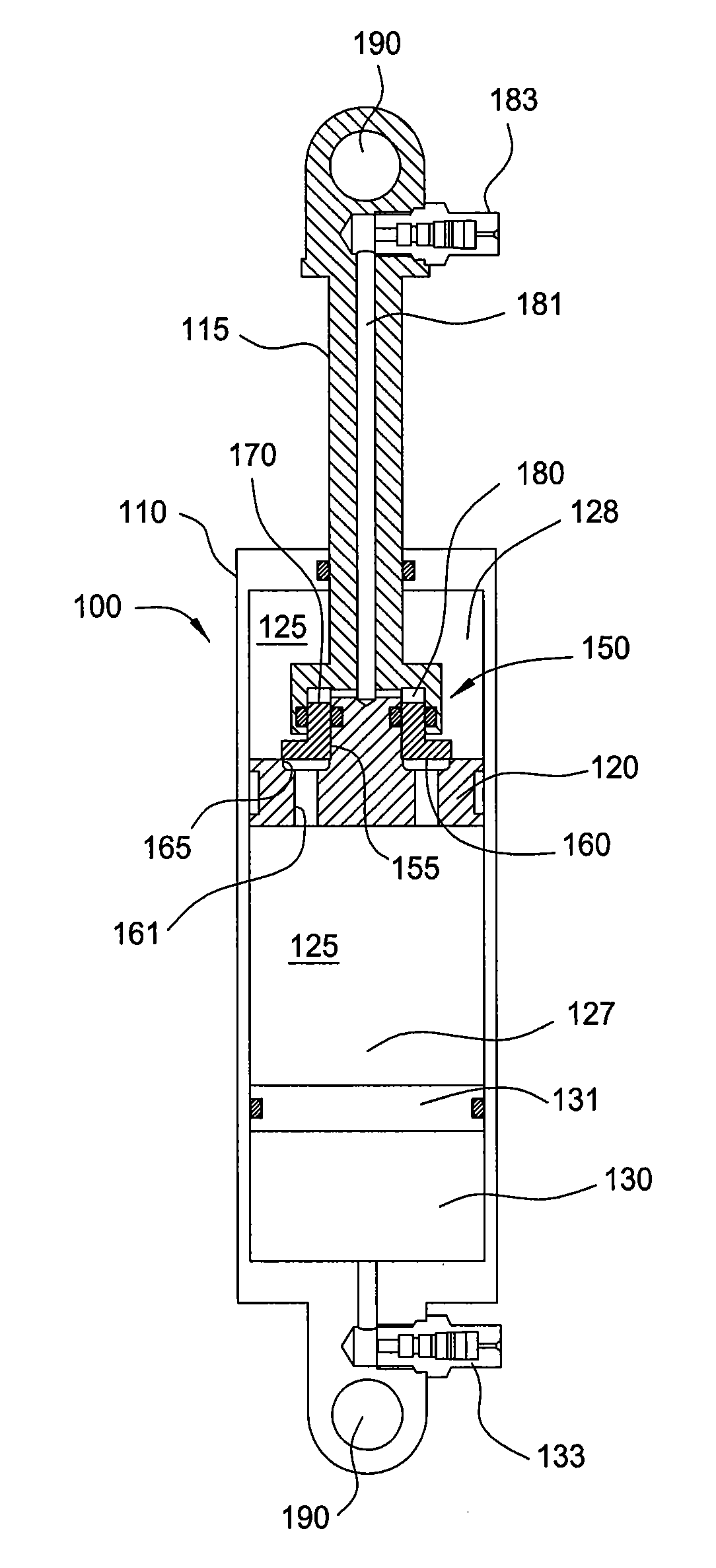
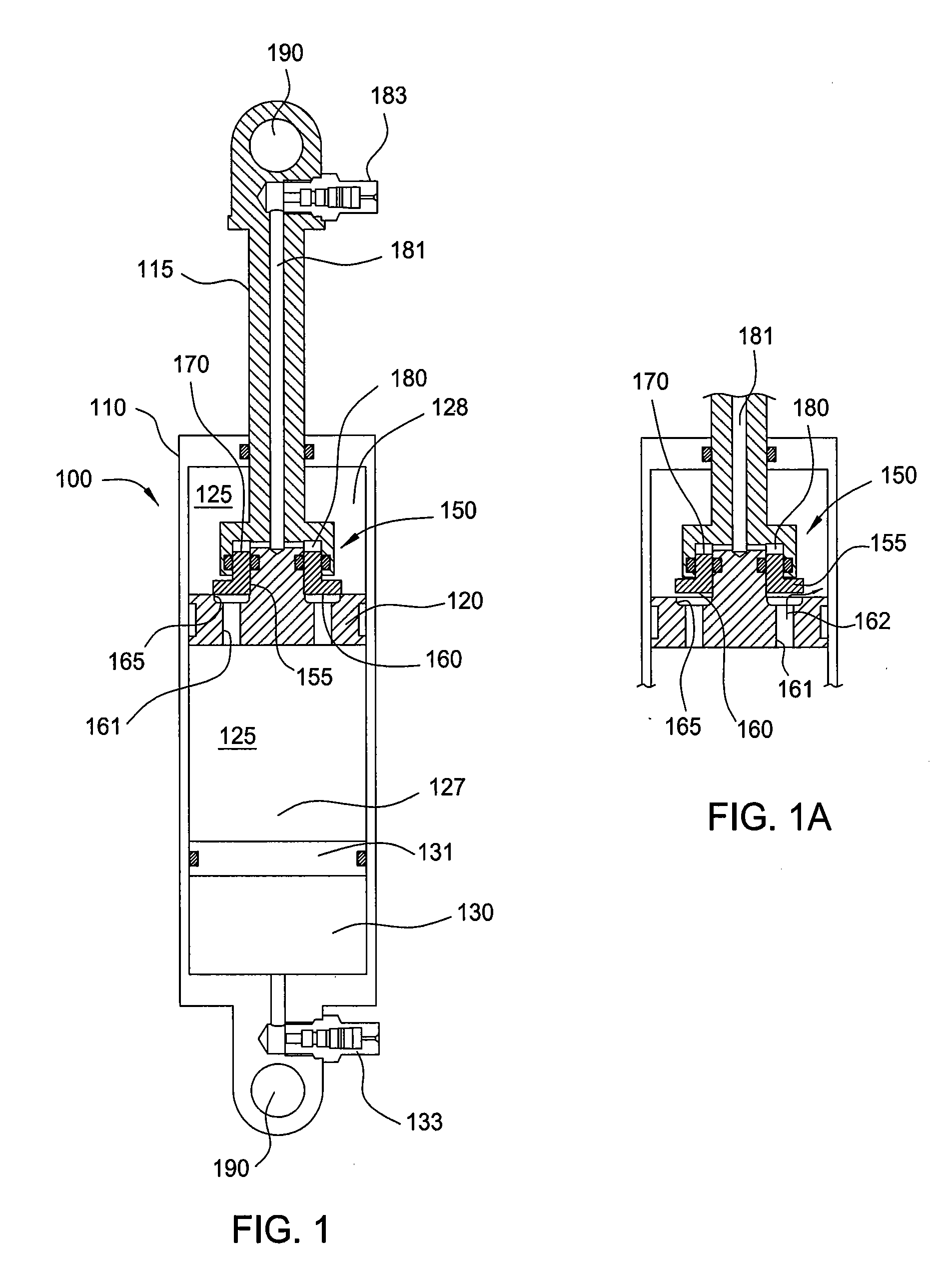
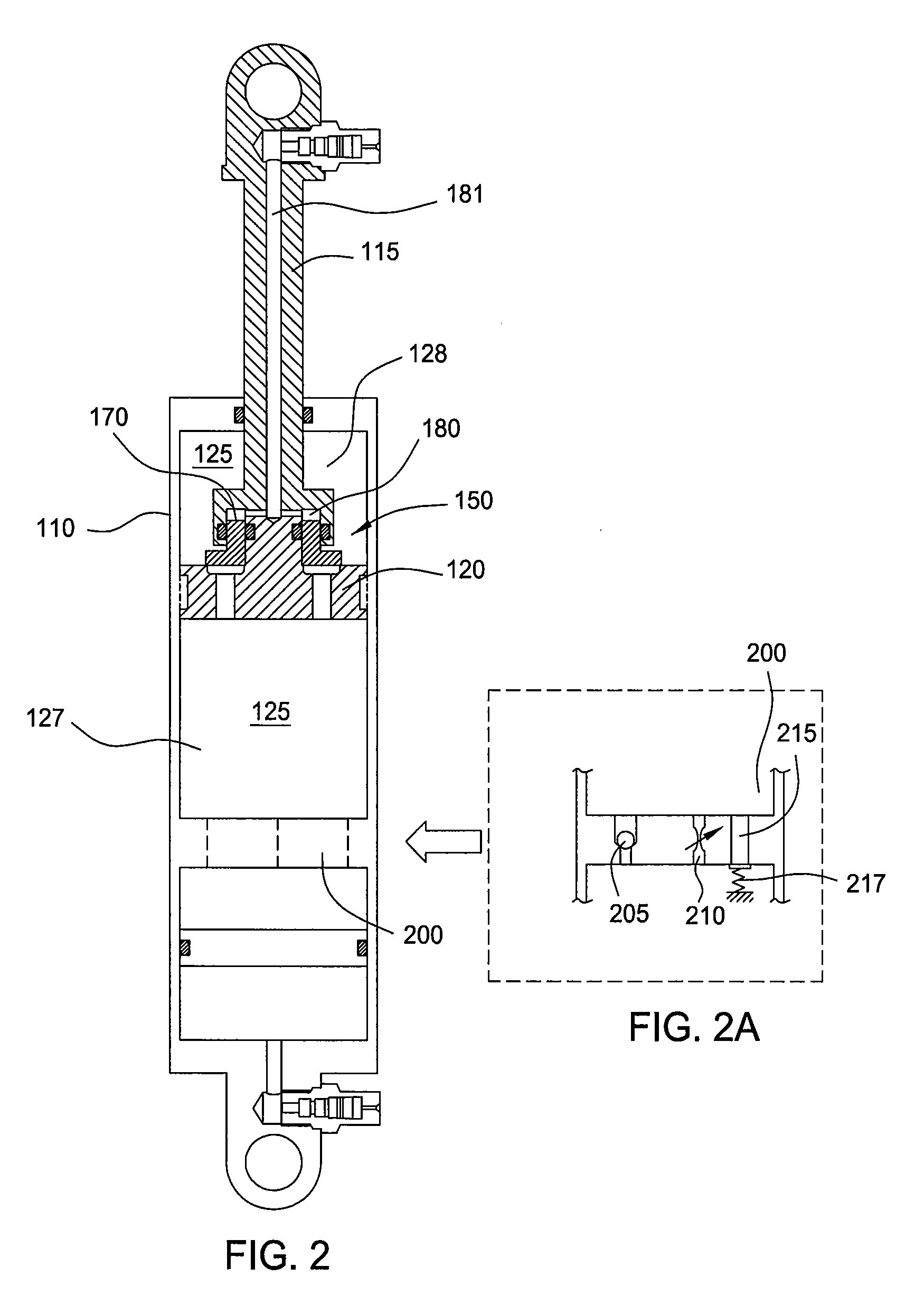
[0016]FIG. 1 is a section view showing one embodiment of a suspension damper 100. The damper includes a housing 110 with a rod 115 and piston 120 arranged to move downward into the housing 110 during a compression stroke and upward back out of the housing during a rebound stroke. A working fluid (e.g. damping fluid such as hydraulic oil) 125 in the housing passes through the piston 120 during each stroke and, depending upon the dampening needs, is metered to control a rate of movement of the piston 120 in the housing 110. A gas filled reservoir 130 at one end of the housing 110 and separated from the working fluid by a floating piston 131 provides additional volume as the rod 115 moves into the housing and displaces the working fluid 125. The gas in the reservoir 130 is user-adjustable via a fill valve 133 (such as for example a Schrader or Presta type gas fill valve) mounted externally and in fluid communication with the reservoir 130. Eyelets 190 formed at each end of the damper 1...


PUM


Abstract

Pressure-sensitive vales are incorporated within a dampening system to permit user-adjustable tuning of a shock absorber. In one embodiment, a pressure-sensitive valve includes an isolated gas chamber having a pressure therein that is settable by a user.

Description

CROSS-REFERENCE TO RELATED APPLICATIONS[0001]This application claims benefit of U.S. provisional patent application Ser. No. 61 / 157,541, filed Mar. 4, 2009. This application is also a continuation-in-part of U.S. patent application Ser. No. 12 / 407,610, filed on Mar. 19, 2009, which claims priority to U.S. provisional patent application Ser. No. 61 / 038,015, filed Mar. 19, 2008. This application is also a continuation-in-part of U.S. patent application Ser. No. 12 / 509,258, filed on Jul. 24, 2009, which claims priority to U.S. provisional patent application Ser. No. 61 / 227,775, filed Jul. 22, 2009. All of these applications are herein incorporated herein, by reference, in their entireties.BACKGROUND OF THE INVENTION[0002]1. Field of the Invention[0003]Embodiments of the present invention generally relate to a suspension system for a vehicle. More particularly, the invention relates to a damper operable in conjunction with a pressure-sensitive valve that affects dampening characteristic...

Claims


Application Information

Patent Timeline
Patent Type & Authority Applications(United States)
IPC IPC(8): B60G17/04F16F9/00F16F9/34F16F9/02
CPCB60G15/12B60G17/0416B60G17/08B60G2202/314B60G2202/322B60G2500/22F16F9/44F16F9/5126B60G17/048B60G2202/152F16F9/34
Inventor WOOTTEN, DENNIS K.FOX, ROBERT C.YABLON, JOSHHAUGEN, DAVID M.
Owner FOX FACTORY
Why Eureka
Try Eureka