Pedestrian protection device for vehicle

Active Publication Date: 2010-09-30
MAZDA MOTOR CORP
View PDF55 Cites 32 Cited by
  • Summary
  • Abstract
  • Description
  • Claims
  • Application Information

AI Technical Summary

Benefits of technology

[0007]The present invention has been devised in view of the above-described matter, and an object of the present invention is to provide a pedest

Problems solved by technology

Therefore, it cannot be said that this hood device performs an impact absorption by

Method used


Image

  • Pedestrian protection device for vehicle
  • Pedestrian protection device for vehicle
  • Pedestrian protection device for vehicle

Examples


embodiment 1

Structure of Front Portion of Vehicle Body

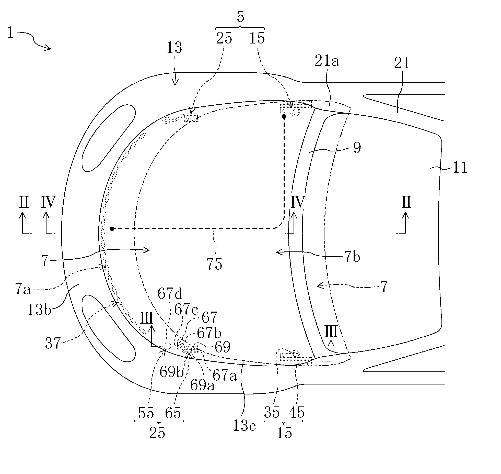
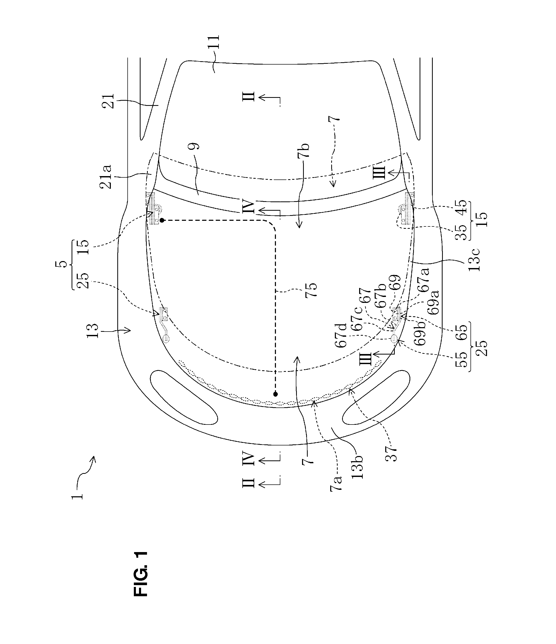
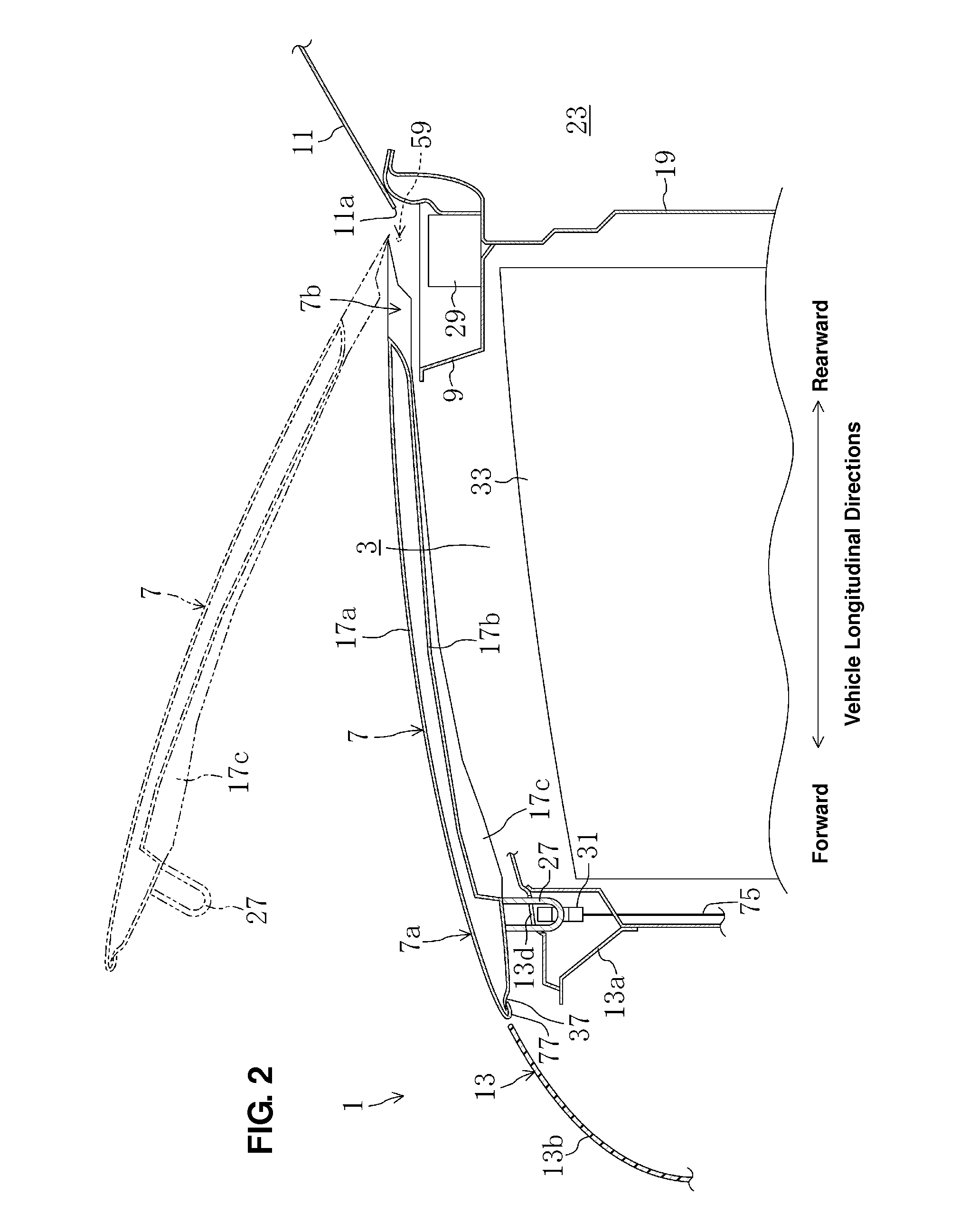
[0042]FIG. 1 is a plan view of a front portion of a vehicle body of a vehicle equipped with a pedestrian protection device for a vehicle according to a first embodiment of the present invention. FIG. 2 is a sectional view taken along line II-II of FIG. 1. A vehicle 1, at a front portion of a vehicle body 13 (hereinafter, referred to as “vehicle body” sometimes), comprises an engine room 3 in which an engine 33 is stored, a cowl box 9 which is provided at an upper portion of a dash panel 19 which partitions the engine room 3 from a vehicle compartment 23, and an engine hood 7 which covers over the engine room 3 as shown in FIGS. 1 and 2.

[0043]The cowl box 9 extends in a vehicle width direction and supports a lower end of a windshield 11 over its whole width. A wiper device (for example, comprising a motor and a cam mechanism of a wiper drive device) 29 is arranged inside the cowl box 9. Front pillars 21, 21 are provided at both side edges of ...

embodiment 2

[0104]A second embodiment comprises another impact lightening means 85′ which is different from the impact lightening means 85 of the above-described first embodiment. Hereinafter, only difference from the first embodiment will be described.

[0105]The impact lightening means 85′ of the present embodiment comprises a hemming portion 77′ (a tip) of the engine hood 7 which is formed so as to extend downwardly as shown in FIG. 13. Thereby, an uncovered sharp tip of the engine hood 7 which has been moved upwardly can be prevented from facing toward the pedestrian, so that the direct contact of the pedestrian with the tip of the engine hood 7 can be avoided.

[0106]Some space is formed between the front end portion of the vehicle body and the front end portion 7a of the engine hood 7 when the engine hood 7 is moved upward. Herein, since the hemming portion 77′ of the engine hood 7 extends downwardly, the above-describe space is made narrower, so that the pedestrian can be also prevented from...

embodiment 3

[0107]A third embodiment comprises another impact lightening means 85″ which is further different from the impact lightening means 85, 85′ of the above-described embodiments. Hereinafter, only difference from the first and second embodiments will be described.

[0108]The impact lightening means 85″ of the present embodiment comprises, as shown in FIGS. 14 and 15, an engaging portion 97 which is provided at the front end portion of the engine hood 7 and a curtain member 93 as a cover member which is provided at the shroud member 13a. The engaging portion 97, which is made from resilient resin, is formed so as to curve rearward in a hook shape. This engaging portion 97 is attached to a lower face of the hemming portion 77 in front of the striker 27.

[0109]The curtain member 93, which is made of a nylon-fiber belt or the like, is provided almost over the whole width of the engine hood 7. This curtain member 93 comprises a base end portion 93a which is fixed to the shroud member 13a at its...


PUM


Abstract

A pedestrian protection device for a vehicle is provided at a vehicle-body front portion which comprises an engine room, a cowl box provided at an upper portion of a dash panel and extending in a vehicle width direction, and an engine hood pivotally supported at the vehicle body via a first hinge provided at a rear end portion so as to cover over the engine room. An engine-hood guide mechanism guides the engine hood upwardly and rearwardly so as to cover at least part of the cowl box when a collision of a pedestrian against a front bumper face is detected or predicted, and lowers the engine hood downwardly when a load acting on the engine hood exceeds a specified load.

Description

BACKGROUND OF THE INVENTION[0001]The present invention relates to a pedestrian protection device for a vehicle which is provided at a front portion of a vehicle body.[0002]In case a pedestrian collides with a traveling vehicle from the front, the pedestrian hits against a bumper at a vehicle's front end first and then may hit against an engine hood covering a vehicle's engine room again as a secondary collision. Therefore, some countermeasure for lightening an impact of the secondary collision has been conventionally applied to the engine hood in order to protect the pedestrian.[0003]In case the pedestrian collides with the bumper, for example, a pedestrian having a small body size tends to hit against a front end portion of the engine hood covering the engine room as the secondary collision, while a pedestrian having a large body size tends to hit against a rear end portion of the engine hood as the secondary collision. Accordingly, vehicles have been recently equipped with the eng...

Claims


Application Information

Patent Timeline
IPC IPC(8): B60R21/34B60R21/38
CPCB60R21/38E05B77/08B60R2021/343
Inventor NAKAURA, MASAKITANAKA, KAZUHIROTAKAYAMA, MASATOSHIIOKA, TADASHI
Owner MAZDA MOTOR CORP
Why Eureka
Try Eureka