Apparatus for Connecting LED Lamps Into Lighting Instruments of a Fluorescent Lamp

Inactive Publication Date: 2010-09-30
KIM CHUL
View PDF3 Cites 20 Cited by
  • Summary
  • Abstract
  • Description
  • Claims
  • Application Information

AI Technical Summary

Benefits of technology

[0016]Accordingly, the present invention has been made keeping in mind the above problems occurring in the prior art, and an object of the present invention is to provide an apparatus for connecting LED lamps to a fluorescent lamp apparatus that enabl

Problems solved by technology

Currently, although most homes generate illumination using fluorescent lamps, the fluorescent lamps have short life spans and low light emission efficiency compared to LED lamps and additionally have the problem of environmental pollution attributable to filled gas, so

Method used


Image

  • Apparatus for Connecting LED Lamps Into Lighting Instruments of a Fluorescent Lamp
  • Apparatus for Connecting LED Lamps Into Lighting Instruments of a Fluorescent Lamp
  • Apparatus for Connecting LED Lamps Into Lighting Instruments of a Fluorescent Lamp

Examples


first embodiment

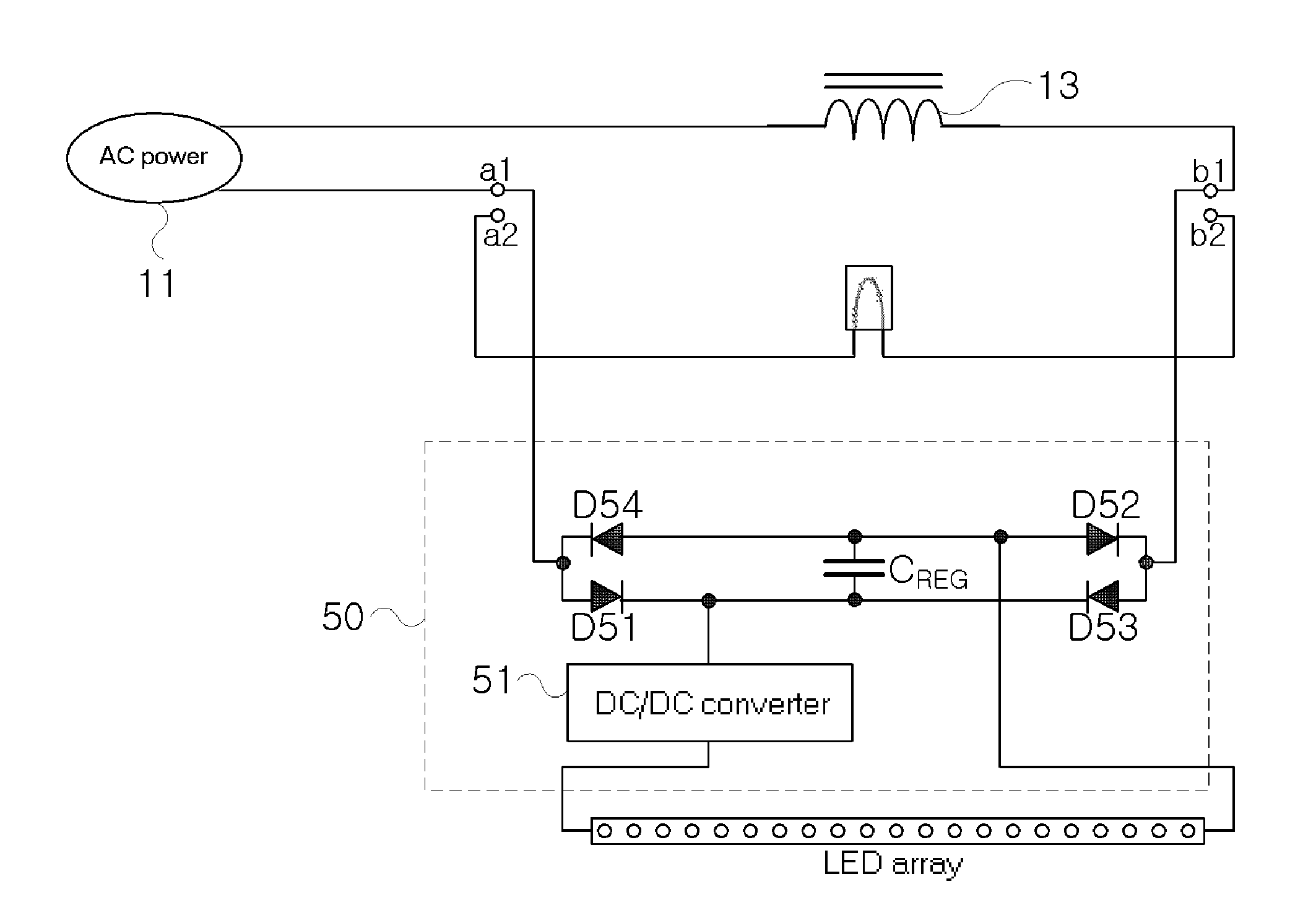
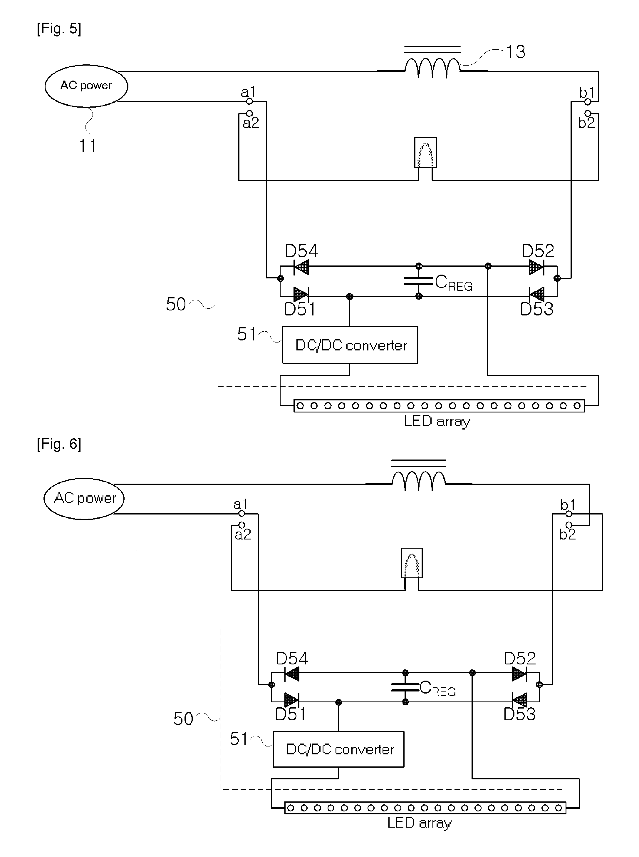
[0032]FIG. 5 shows an apparatus 50 for connecting LED lamps to a fluorescent lamp apparatus according to the present invention, which is an embodiment in which LED lamps are connected to a magnetic glow starter-type fluorescent lamp apparatus.

[0033]This apparatus 50 for connecting LED lamps is connected in series to an AC power supply unit 11 and a ballast 13, each of which is connected to one of the two connection terminals on each side of the fluorescent lamp mounting unit of the fluorescent lamp apparatus. In the case where a connection terminal a1 is connected to the AC power supply unit 11 and a connection terminal b1 is connected to the ballast 13, as shown in FIG. 5, this apparatus 50 for connecting LED lamps should be connected between the connection terminal a1 and the connection terminal b1.

[0034]The apparatus 50 for connecting LED lamps includes bridge diodes D51, D52, D53 and D54 for rectifying input power, a smoothing capacitor CREG for smoothing power full-wave-rectifi...

second embodiment

[0038]FIG. 8 shows an apparatus for connecting LED lamps to a fluorescent lamp apparatus according to the present invention in which the problem of the apparatus for connecting LED lamps shown in FIG. 5 has been overcome, which is an embodiment in which LED lamps are connected to a magnetic glow starter-type fluorescent lamp apparatus. The apparatus for connecting LED lamps includes two bridge diodes D81˜D88 connected to first and second connection terminals on the first side of the fluorescent lamp mounting unit and to third and fourth connection terminals on the second side and configured to full-wave-rectify AC power conducted between one arbitrary connection terminal on the first side and one arbitrary connection terminal on the second side, a smoothing capacitor CREG configured to smooth the full-wave-rectified power, and an LED lamp power supply unit configured to convert the smoothed DC power into LED lamp driving power. The output power of the LED lamp power supply unit is s...


PUM


Abstract

Disclosed herein is an apparatus for connecting Light-Emitting Diode (LED) lamps to a fluorescent lamp apparatus. The fluorescent lamp apparatus is provided with a fluorescent lamp mounting unit having an Alternating Current (AC) power supply unit, a ballast, two connection terminals on the first side thereof and two connection terminals on the second side thereof. The apparatus of the present invention includes a bridge diode for full-wave-rectifying AC current conducted between a first-side connecting terminal connected to the AC power supply unit and a second-side connection terminal connected to the ballast, a smoothing capacitor for smoothing the power full-wave-rectified by the bridge diode and outputting Direct Current (DC) power, and an LED lamp power supply unit for converting the smoothed DC power into LED lamp driving power and outputting the LED lamp driving power to the LED lamps.

Description

BACKGROUND OF THE INVENTION[0001]1. Field of the Invention[0002]The present invention relates to an apparatus for connecting Light-Emitting Diode (LED) lamps to a fluorescent lamp apparatus[0003]2. Description of Related Art[0004]Fluorescent lamps are lighting devices that are most widely used today along with incandescent lamps because the fluorescent lamps can achieve economical and high illuminance in buildings, factories, homes and the like.[0005]A fluorescent lamp apparatus includes an ignition circuit for lighting a fluorescent lamp first and a ballast for maintaining the lighting of the fluorescent lamp after the lighting of the fluorescent lamp. The ignition circuit is formed of a high voltage generation circuit for generating electric discharge in a fluorescent lamp first, and a ballast having a negative resistance characteristic for maintaining the lighting of a discharge tube after the lighting of the discharge tube is used as the ballast.[0006]Such fluorescent lamp appar...

Claims


Application Information

Patent Timeline
IPC IPC(8): F21V23/00
CPCH05B33/0809H05B33/0821Y02B20/386Y02B20/383Y02B20/348Y02B20/30H05B45/39H05B45/3578H05B41/24H05B41/14H05B45/40H05B45/3725H05B31/50
Inventor KIM, CHUL
Owner KIM CHUL
Why Eureka
Try Eureka