
Primary-side based control of secondary-side current for a transformer

a transformer and secondary-side current technology, applied in the field of signal processing, can solve the problems of difficult monitoring of changes in the secondary-side load current isub>load/sub>(t)

Active Publication Date: 2010-09-30
SIGNIFY HLDG BV
View PDF99 Cites 128 Cited by
  • Summary
  • Abstract
  • Description
  • Claims
  • Application Information

AI Technical Summary

Benefits of technology

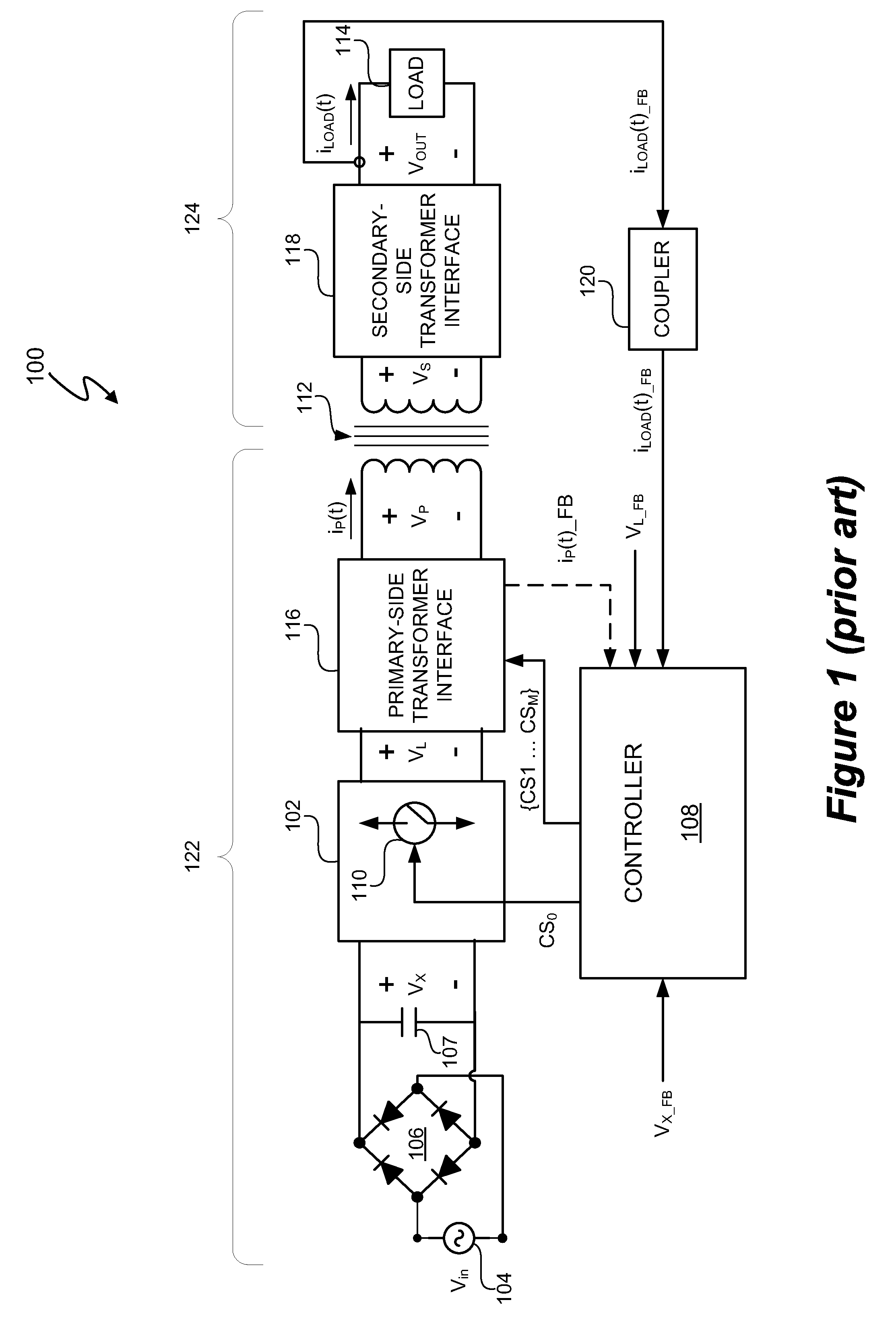
[0017]To regulate the secondary-side load current iLOAD(t), controller 108 utilizes feedback signal iLOAD(t)—<sup2>FB < / sup2>to generate switch control signals CS1 . . . CSM. Feedback signal iLOAD(t)—<sup2>FB < / sup2>represents the secondary-side load current iLOAD(t). Power control system 100 includes coupler 120 to receive feedback signal iLOAD(t)FB. The feedback signal iLOAD(t)—<sup2>FB < / sup2>is, for example, a current or voltage that represents the value of secondary-side current iLOAD(t). Coupler 120 is, for example, an optical coupler that maintains isolation between the primary-side 122 and secondary-side 124 of power control system 100. In another embodiment, coupler 120 is a resistor. When using a resistor, insulation of LOAD 114 and other components can be used to address safety concerns. In any event, the coupler 120 and any auxiliary materials, such as insulation, add cost to power control system 100.

Problems solved by technology

Accordingly, it is very difficult to monitor changes in the secondary-side load current iLOAD(t) without actually sampling the secondary-side current iLOAD(t).

Method used


Image

  • Primary-side based control of secondary-side current for a transformer
  • Primary-side based control of secondary-side current for a transformer
  • Primary-side based control of secondary-side current for a transformer

Examples


Embodiment Construction

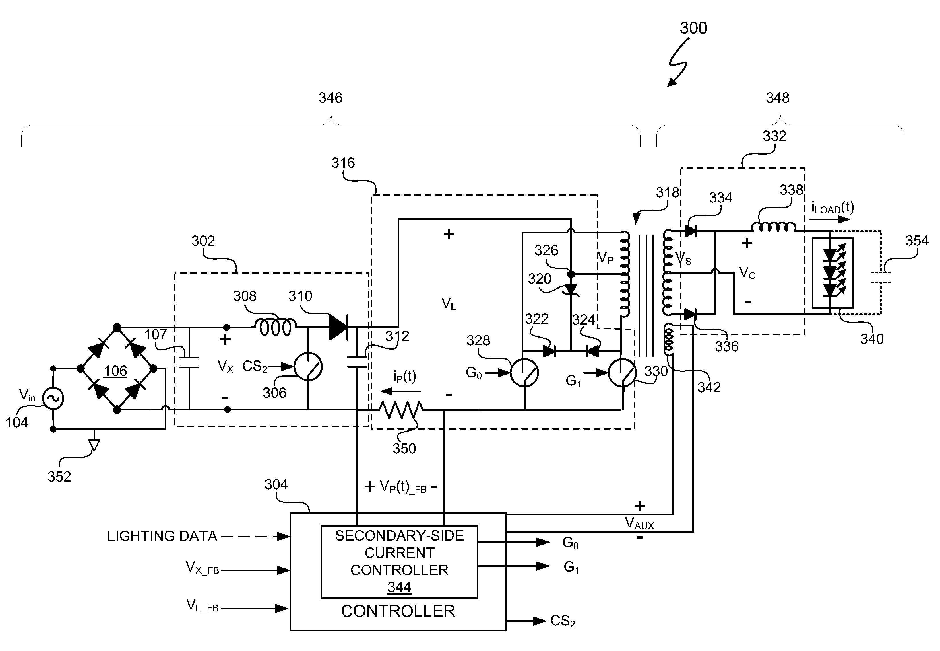
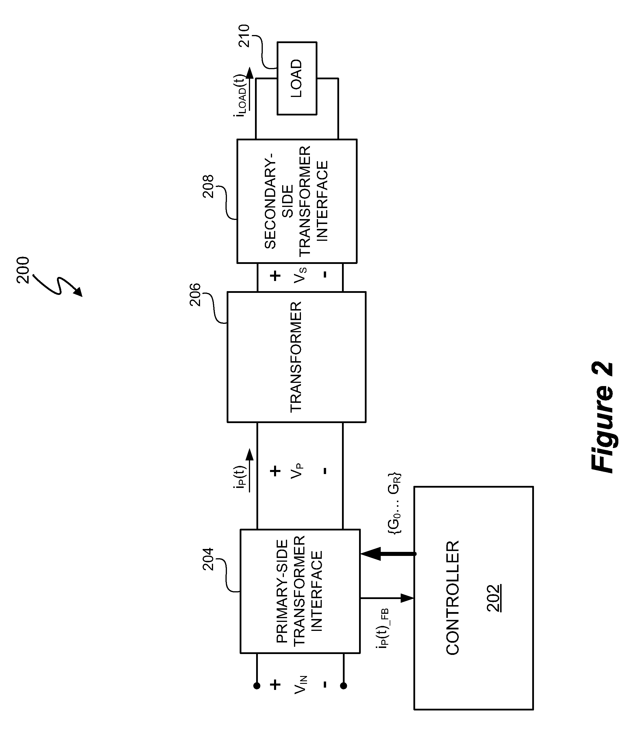
[0033]In at least one embodiment, a power control system includes a transformer, such as an isolation transformer, and a controller regulates a current on a secondary-side of the transformer based on an observed primary-side signal value. In at least one embodiment, the controller is configured to generate one or more duty cycle modulated switch control signals to control a voltage on a primary-side of the transformer based on the observed primary-side signal value and the secondary-side current represents a load current into a load and out of a filter coupled to a rectifier coupled to the secondary-side of the transformer. In at least one embodiment, the load includes one or more LEDs. In at least one embodiment, the primary-side signal value is a sample of a current in the primary-side windings of the transformer. “Regulation” of a particular signal means that the signal can be controlled with less than a 10% error. In at least one embodiment, the controller regulates the load cur...


PUM


Abstract

A power control system includes a transformer and a controller regulates a current on a secondary-side of the transformer based on a primary-side signal value. In at least one embodiment, the secondary-side current is a current out of a filter coupled to a rectifier and the secondary-side of the transformer and into a load. In at least one embodiment, the primary-side signal value is a sample of a current in the primary-side windings of the transformer. In at least one embodiment, the primary-side signal value represents a sample value of a primary-side transformer current. Proper timing of sampling the primary-side signal value substantially eliminates contributions of a transformer magnetizing current from the primary-side transformer current sample. Sampling the primary-side signal value when contributions of the transformer magnetizing current are substantially eliminated allows at least an average of the secondary-side current to be determined from the primary-side signal value.

Description

CROSS REFERENCE TO RELATED APPLICATIONS[0001]This application claims the benefit under 35 U.S.C. §119(e) of U.S. Provisional Application No. 61 / 120,455, filed Dec. 7, 2008, and entitled “Power Converter With Primary Side Current Control.” U.S. Provisional Application No. 61 / 120,455 includes exemplary systems and methods and is incorporated by reference in its entirety.BACKGROUND OF THE INVENTION[0002]1. Field of the Invention[0003]The present invention relates in general to the field of signal processing, and more specifically to a system and method that includes primary-side based control of secondary-side current for a transformer.[0004]2. Description of the Related Art[0005]Power control systems often utilize a switching power converter to convert alternating current (AC) voltages to direct current (DC) voltages or DC-to-DC. Power control systems often provide power factor corrected and regulated output voltages to many devices that utilize a regulated output voltage. Switching p...

Claims


Application Information

Patent Timeline
Patent Type & Authority Applications(United States)
IPC IPC(8): H05B37/02
CPCH02M3/33523H05B33/0851H05B33/0815H05B45/10H05B45/12H05B45/3725H05B45/375H05B45/38H05B45/382H05B45/39
Inventor MELANSON, JOHN L.
Owner SIGNIFY HLDG BV
Learn More