Antenna device, conversion adaptor, and receiver

a technology of conversion adaptor and antenna device, which is applied in the direction of coupling device details, coupling device connection, collapsible antenna means, etc., can solve the problems of undesired large size of antenna device, complicated process of manufacturing antenna device, and high cost, so as to minimize the size and cost of the device, reduce the number of components and the number of manufacturing steps, and prevent the effect of receiver sensitivity from deteriorating

Inactive Publication Date: 2010-09-30
SONY SEMICON SOLUTIONS CORP
View PDF13 Cites 12 Cited by
  • Summary
  • Abstract
  • Description
  • Claims
  • Application Information

AI Technical Summary

Benefits of technology

[0017]According to any embodiment of the present invention, there is provided any of an antenna device, a conversion adapter, and a receiver, which can reduce the number of components and the number of man

Problems solved by technology

However, the antenna device disclosed in Japanese Unexamined Patent Application Publication No. 2007-281832 is typically provides with a complicated structure for connection between a plug and an antenna member.
Thus, the antenna device is typically produced in undesired large size at a high cost because of using increased numbers of parts and working processes.
Furthermore, such a complicated process of manufacturing the antenna device may

Method used


Image

  • Antenna device, conversion adaptor, and receiver
  • Antenna device, conversion adaptor, and receiver
  • Antenna device, conversion adaptor, and receiver

Examples


first embodiment

1. First Embodiment

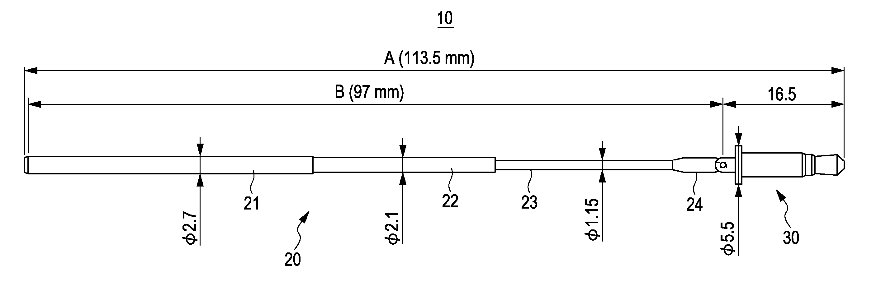
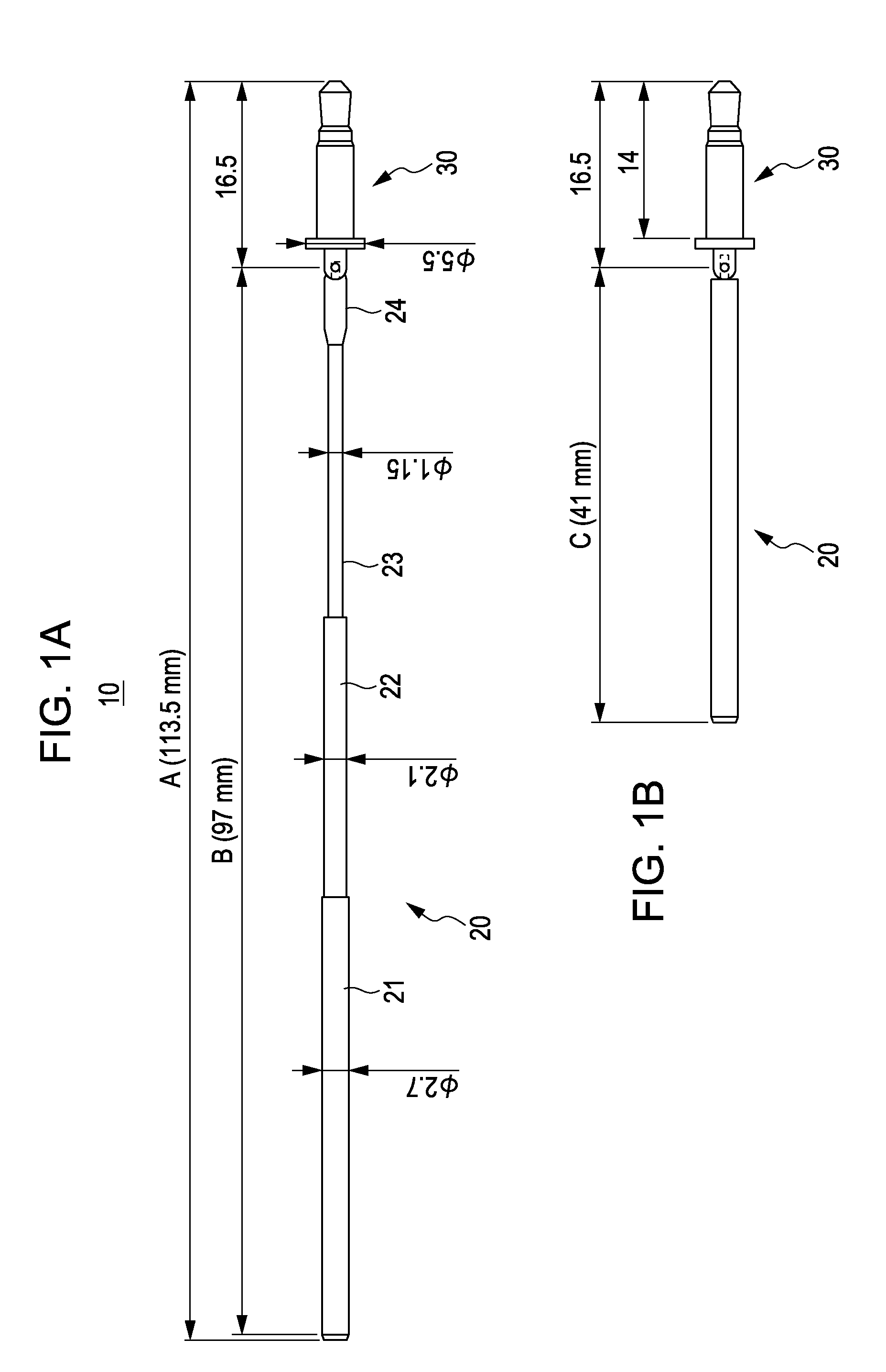
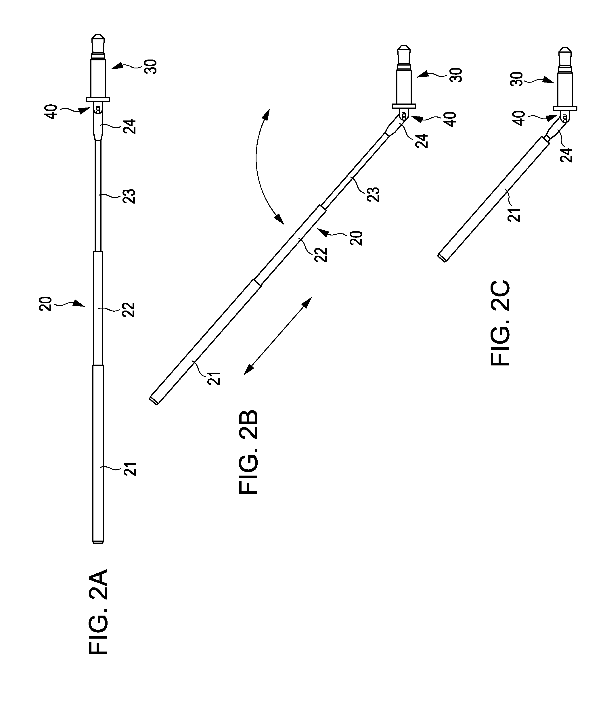
[0057]FIG. 1A and FIG. 1B are diagrams illustrating an exemplary configuration of an antenna device as a first embodiment of the present invention and represent different states of the antenna device, respectively. Specifically, FIG. 1A shows that the antenna device is fully elongated and FIG. 1B shows that the antenna device is retracted. Furthermore, FIGS. 2A to 2C are diagrams illustrating an exemplary configuration of an antenna device as a first embodiment of the present invention and represent different states of the antenna device, respectively. Specifically, FIG. 2A shows that the antenna device is fully extended, FIG. 2B shows that the antenna device is elongated in a rotatable manner, and FIG. 2C shows that the antenna device is retracted in a rotatable manner.

[0058]The antenna device 10 of the first embodiment includes a retractable rod antenna element 20, a disk-shaped, round plug 30 removably fit in a round jack arranged in an electronic apparatus, su...

second embodiment

2. Second Embodiment

[0084]FIG. 8 is a diagram illustrating an exemplary configuration of an antenna device as a second embodiment of the present invention.

[0085]The antenna device 10A of the second embodiment has the same configuration as that of the first embodiment, with the exception that a round type plug 30A is formed as a multipole plug.

[0086]A ground sleeve portion 311 or the like is fundamentally formed on the base side of the round multipole plug 30A. A tip portion 312 for signal or left channel is formed on the end side of the plug 30A. An insulated ring portion 313 for right channel is formed between the sleeve portion 311 and the tip portion 312. Part of the rotation mechanism section 40A to be connected to the connection part 24 of the rod antenna element 20 is formed on one end of the sleeve portion 311.

[0087]The round multipole plug 30A of the antenna device 10A according to the second embodiment can be easily formed by machining the portion of the antenna device 10A ...

third embodiment

3. Third Embodiment

[0101]FIG. 14A and 14B are diagrams illustrating an exemplary configuration of an antenna device as a third embodiment of the present invention. FIG. 14A and FIG. 14B represent different states of the antenna device, respectively.

[0102]The antenna device 10B of the third embodiment has the same configuration as that of the first embodiment, with the exception that a hole 25 for connecting a strap STRP is formed in the end of the rod antenna element 20b.

[0103]As shown in FIG. 14B, for example, the antenna device 10B of the present embodiment may be attached to a cell phone 50 while being attached to the conversion adaptor 60 and may be then carried using the strap STRP.


PUM


Abstract

An antenna device includes a round plug having a rotation mechanism section on one end thereof, where round plug is removably attached to a round jack arranged in an electronic apparatus; and a rod antenna element. In the antenna device, the rod antenna element is connected to the rotation mechanism section of the round plug and rotatable in a predetermined direction.

Description

BACKGROUND OF THE INVENTION[0001]1. Field of the Invention[0002]The present invention relates to an antenna device, a conversion adaptor, and a receiver, which are applicable to portable electronics, such as potable AV equipment and cell phones.[0003]2. Description of the Related Art[0004]Rod-like antennas have been widely known as antenna devices. A helical antenna is also shaped like a rod and known as one of the rod-like antennas. The helical antenna includes a short, coiled spring-shape antenna element housed in a flexible tube. For small portable television sets, radio sets, and the like, telescopic rod antennas are used.[0005]In addition, various kinds of rod antennas provided with rotation mechanisms, such as hinges, have been proposed (see, for example, Japanese Unexamined Patent Application Publication Nos. 2007-67774, 2002-26622, and 11-355019. The rod antennas disclosed in these patent documents typically desire complicated structures for the rotation mechanism. For addre...

Claims


Application Information

Patent Timeline
IPC IPC(8): H01Q1/50H01Q3/02H01Q1/24H01R13/66
CPCH01Q1/084H01Q1/10H01Q1/1207H01Q1/273H01R2201/02H01R24/58H01R31/06H01R2103/00H01Q1/44
Inventor MUKAI, KOICHIYOSHINO, YOSHITAKAKOMORI, CHISATOMIYAZAKI, YUUJI
Owner SONY SEMICON SOLUTIONS CORP
Why Eureka
Try Eureka