Droplet ejection device

a technology of ejection device and droplet, which is applied in printing and other directions, can solve the problems of broken meniscus at the ejection aperture and the possibility of liquid ejection

Active Publication Date: 2010-09-30
FUJIFILM CORP
View PDF5 Cites 48 Cited by
  • Summary
  • Abstract
  • Description
  • Claims
  • Application Information

AI Technical Summary

Benefits of technology

[0008]In consideration of the matter described above, the present invention will provide a droplet ejection device capab

Problems solved by technology

As a result, meniscuses at the ejection apertures are br

Method used


Image

  • Droplet ejection device
  • Droplet ejection device
  • Droplet ejection device

Examples


first exemplary embodiment

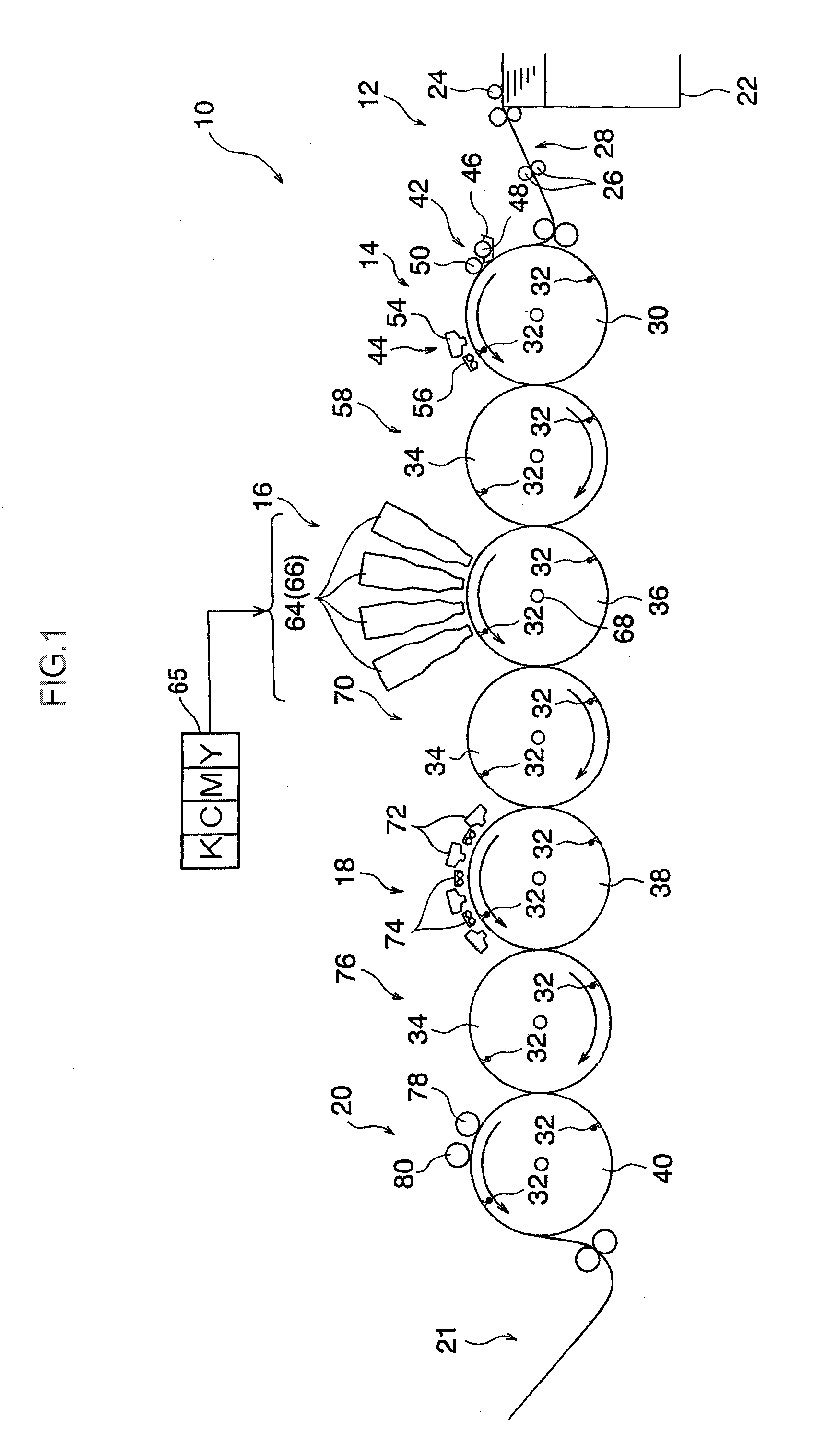
[0026]FIG. 1 shows an overall view of an inkjet recording device illustrating exemplary embodiments of the droplet ejection device. As illustrated in FIG. 1, an inkjet recording device 10 is provided with a paper supply conveyance section 12 that supplies and conveys sheet paper (hereinafter referred to as paper) P which serves as a recording medium, at an upstream side of a conveyance direction of the paper P. Along the conveyance direction of the paper P to the downstream side from the paper supply conveyance section 12, an application section 14, a recording section 16, an ink drying section 18, a fixing section 20 and an ejection section 21 are provided. The application section 14 applies a processing liquid to an image recording face of the paper P (hereinafter referred to as the recording face). The recording section 16 records an image on the recording face of the paper P. The ink drying section 18 dries the image recorded on the recording face. The image fixing section 20 fi...

second exemplary embodiment

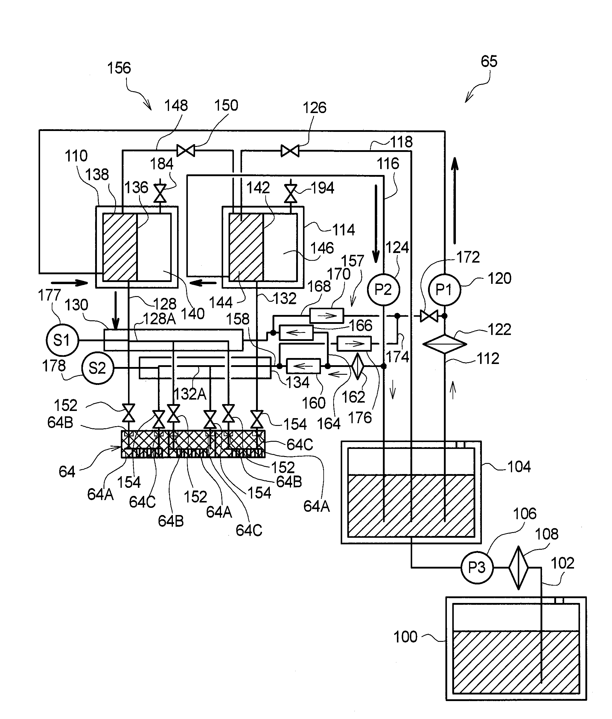
[0108]In the first exemplary embodiment, an example has been described of a case in which excess pressure on ink in the flow paths 128A and 132A is ameliorated using the differential pressure valves 160, 166, 170 and 176. In this second exemplary embodiment, a case is described in which excess pressure on ink in the flow paths 128A and 132A is ameliorated using electromagnetic valves. Here, in this second exemplary embodiment, the same reference numerals are assigned to members that are the same as in the inkjet recording device 10 relating to the first exemplary embodiment and will not be described; only portions that differ from the first exemplary embodiment are described.

[0109]FIG. 8 shows a structural diagram illustrating structure of the head 64 and an ink storage / charging section 65B relating to the second exemplary embodiment.

[0110]As shown in FIG. 8, an inkjet recording device 10B differs from the inkjet recording device 10 relating to the first exemplary embodiment in that...


PUM


Abstract

A droplet ejection device includes a liquid ejection head, a supply flow path, a supply pump, and a supply flow path pressurizer. The supply flow path supplies the liquid to the head and for which a first depressurization threshold is specified in advance. The supply pump sucks the liquid, pressurizes the sucked liquid and supplies the sucked liquid to the head via the supply flow path, and keeps a pressure of liquid in the supply flow path near to a predetermined supply flow path target pressure. The supply flow path pressurizer pressurizes the pressure of liquid in the supply flow path if the pressure of liquid in the supply flow path falls to less than or equal to the first depressurization threshold.

Description

CROSS-REFERENCE TO RELATED APPLICATION[0001]This application claims priority under 35 USC 119 from Japanese Patent Application No. 2009-074920 filed on Mar. 25, 2009, the disclosure of which is incorporated by reference herein.BACKGROUND OF THE INVENTION[0002]1. Field of the Invention[0003]The present invention relates to a droplet ejection device that ejects a liquid.[0004]2. Description of the Related Art[0005]An inkjet recording device is known (for example, see Japanese Patent Application Laid-Open (JP-A) No. 2008-513245) that includes a head provided with ejection apertures that eject a liquid for image recording (for example, ink), and records an image by ejecting droplets from the ejection apertures at a recording medium (for example, paper, a transparent substrate or the like).[0006]This type of inkjet recording device, by supplying liquid stored in a storage tank to the head via supply piping with a supply pump and draining liquid in the head to the storage tank with a drai...

Claims


Application Information

Patent Timeline
IPC IPC(8): B41J2/175
CPCB41J2/515B41J2/175
Inventor KATADA, MASAHITOKATADA, YUKOKATADA, NATSUKIKATADA, DAICHI
Owner FUJIFILM CORP
Why Eureka
Try Eureka