Method and system for detecting particle contamination in an immersion lithography tool

a technology of immersion lithography and particle contamination, applied in the field of microstructure fabrication, can solve problems such as significant downtime, and achieve the effect of improving particle detection capabilities and significant downtime of complex immersion lithography systems

Inactive Publication Date: 2010-09-30
GLOBALFOUNDRIES US INC
View PDF5 Cites 32 Cited by
  • Summary
  • Abstract
  • Description
  • Claims
  • Application Information

AI Technical Summary

Benefits of technology

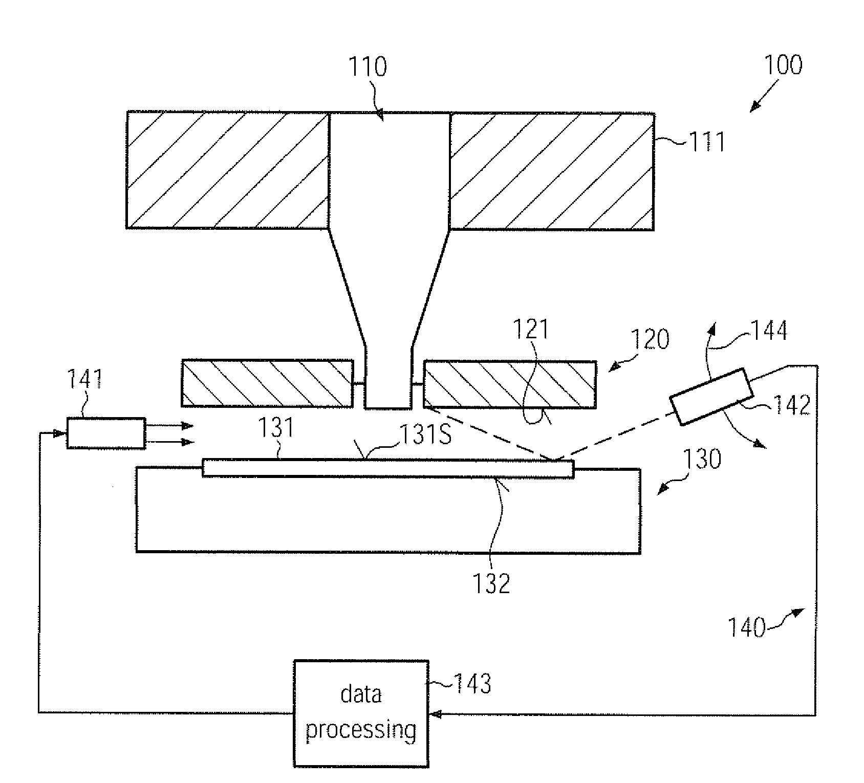
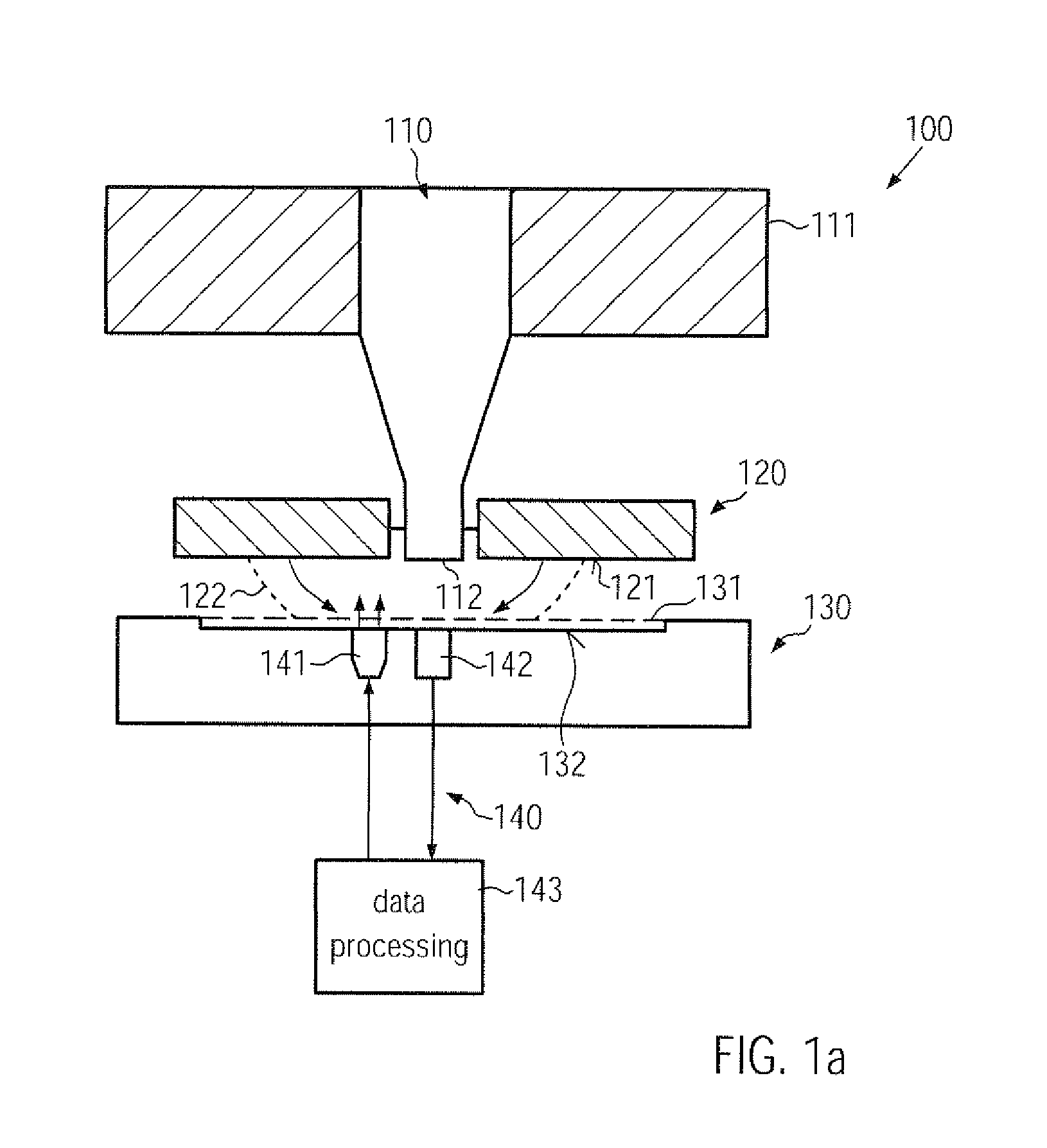
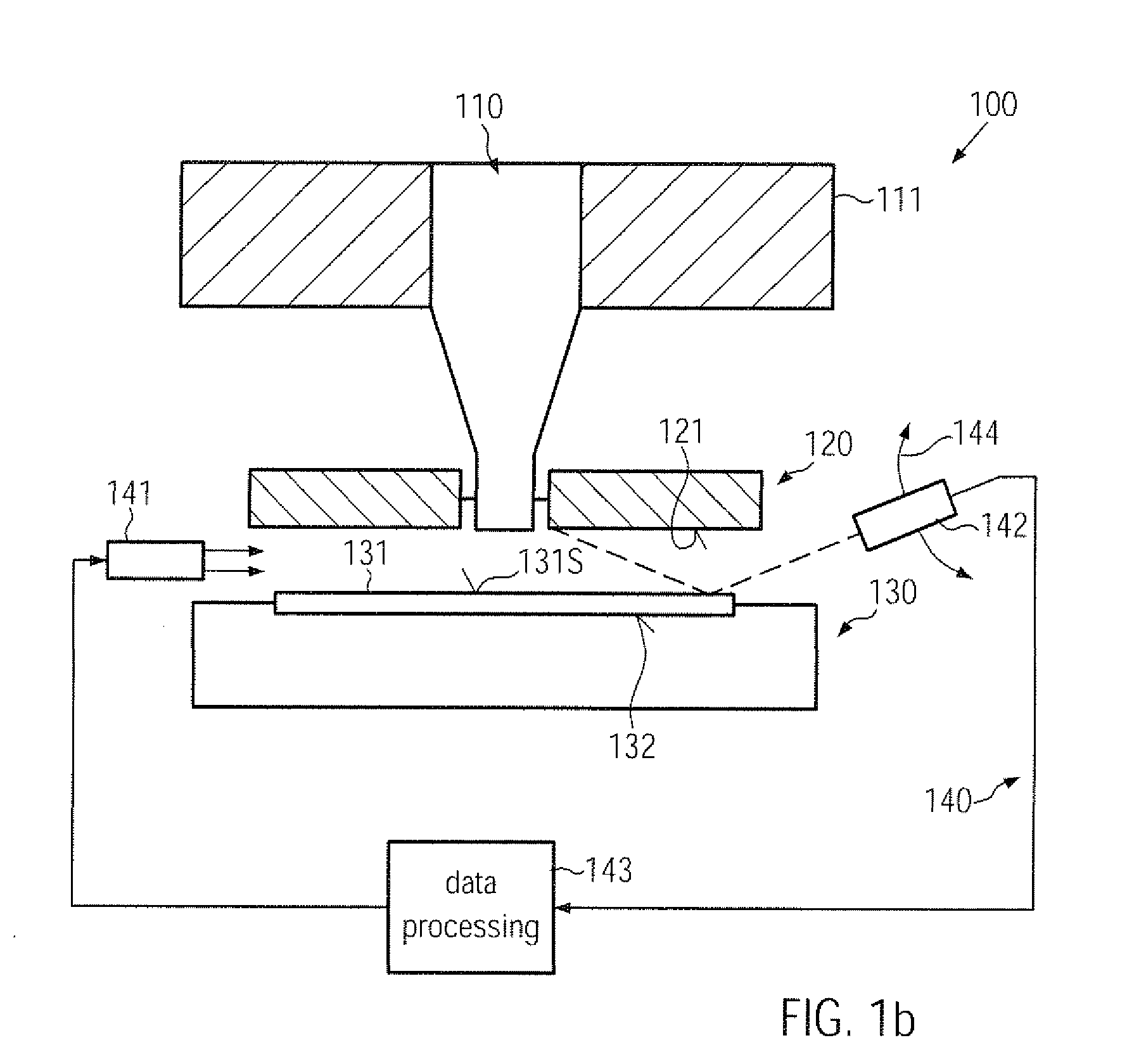
[0008]Generally, the present disclosure provides immersion lithography tools and techniques for operating the same in which enhanced particle detection capabilities may be provided in order to appropriately determine the state of at least a hood surface of the lithography system. To this end, an optical detection system may be provided in combination with the lithography system to provide the capability for “inspecting” the surface state of the hood surface or determining the status thereof on the basis of optical measurement data, which may thus be obtained without exposing the interior of the lithography system to ambient air. Consequently, the optical measurement data may be obtained at any appropriate time, for instance between the processing of substrates or, in other illustrative embodiments disclosed herein, in the presence of a substrate, for instance a dedicated test substrate, a product substrate and the like, wherein, based on the optical measurement data, a cleaning process may be initiated depending on the actual state of the hood surface. Consequently, the cleaning processes may be performed “on demand” rather than on a regular basis, which conventionally may contribute to significant down times of complex immersion lithography systems.

Problems solved by technology

Consequently, the cleaning processes may be performed “on demand” rather than on a regular basis, which conventionally may contribute to significant down times of complex immersion lithography systems.

Method used


Image

  • Method and system for detecting particle contamination in an immersion lithography tool
  • Method and system for detecting particle contamination in an immersion lithography tool
  • Method and system for detecting particle contamination in an immersion lithography tool

Examples


Embodiment Construction

[0018]Various illustrative embodiments of the invention are described below. In the interest of clarity, not all features of an actual implementation are described in this specification. It will of course be appreciated that in the development of any such actual embodiment, numerous implementation-specific decisions must be made to achieve the developers' specific goals, such as compliance with system-related and business-related constraints, which will vary from one implementation to another. Moreover, it will be appreciated that such a development effort might be complex and time-consuming, but would nevertheless be a routine undertaking for those of ordinary skill in the art having the benefit of this disclosure.

[0019]The present subject matter will now be described with reference to the attached figures. Various structures, systems and devices are schematically depicted in the drawings for purposes of explanation only and so as to not obscure the present disclosure with details ...


PUM


Abstract

In an immersion lithography tool, the status of the immersion hood surface may be estimated on the basis of an inline detection system that generates optical measurement data. For example, a digital imaging system may be implemented in order to obtain optical measurement data without requiring exposure of the interior of the lithography tool to ambient air. In other cases, other optical measurement techniques, such as FTIR and the like, may be applied.

Description

BACKGROUND OF THE INVENTION[0001]1. Field of the Invention[0002]The present disclosure relates to the field of fabricating microstructures, such as integrated circuits, and, more particularly, to immersion lithography processes and tools.[0003]2. Description of the Related Art[0004]The fabrication of microstructures, such as integrated circuits, requires tiny regions of precisely controlled size to be formed in a material layer of an appropriate substrate, such as a silicon substrate, a silicon-on-insulator (SOI) substrate or other suitable carrier materials. These tiny regions of precisely controlled size are generated by patterning the material layer by performing lithography, etch, implantation, deposition, oxidation processes and the like, wherein, typically, at least in a certain stage of the patterning process, a mask layer may be formed over the material layer to be treated to define these tiny regions. Generally, a mask layer may consist of or may be formed by means of a lay...

Claims


Application Information

Patent Timeline
Patent Type & Authority Applications(United States)
IPC IPC(8): G03B27/52
CPCG03F7/70341G03F7/70916G03F7/7085
Inventor SELTMANN, ROLFWIRTZ, RENE
Owner GLOBALFOUNDRIES US INC
Why Eureka
Try Eureka