Optical device, optical scanner, and image forming apparatus

Inactive Publication Date: 2010-09-30
SEIKO EPSON CORP
View PDF2 Cites 0 Cited by
  • Summary
  • Abstract
  • Description
  • Claims
  • Application Information

AI Technical Summary

Benefits of technology

[0007]An advantage of some aspects of the invention is to provide an optical device, an optical scanner, and an image forming apparatus capable of reducing the amount of stray resulting from the light incident on portions other than a movable plate.

Problems solved by technology

As a result, the light incident on the portions other than the movable plate could disadvantageously become stray light, for example, in an area to which the light reflected off the movable plate is directed and on other optical devices, mirrors, and screens (including screens irradiated with light via other optical devices, mirrors, and other components) including the area to which the light reflected off the movable plate is directed.

Method used


Image

  • Optical device, optical scanner, and image forming apparatus
  • Optical device, optical scanner, and image forming apparatus
  • Optical device, optical scanner, and image forming apparatus

Examples


Embodiment Construction

[0030]Embodiments of the invention will be described below with reference to the drawings.

Optical Device

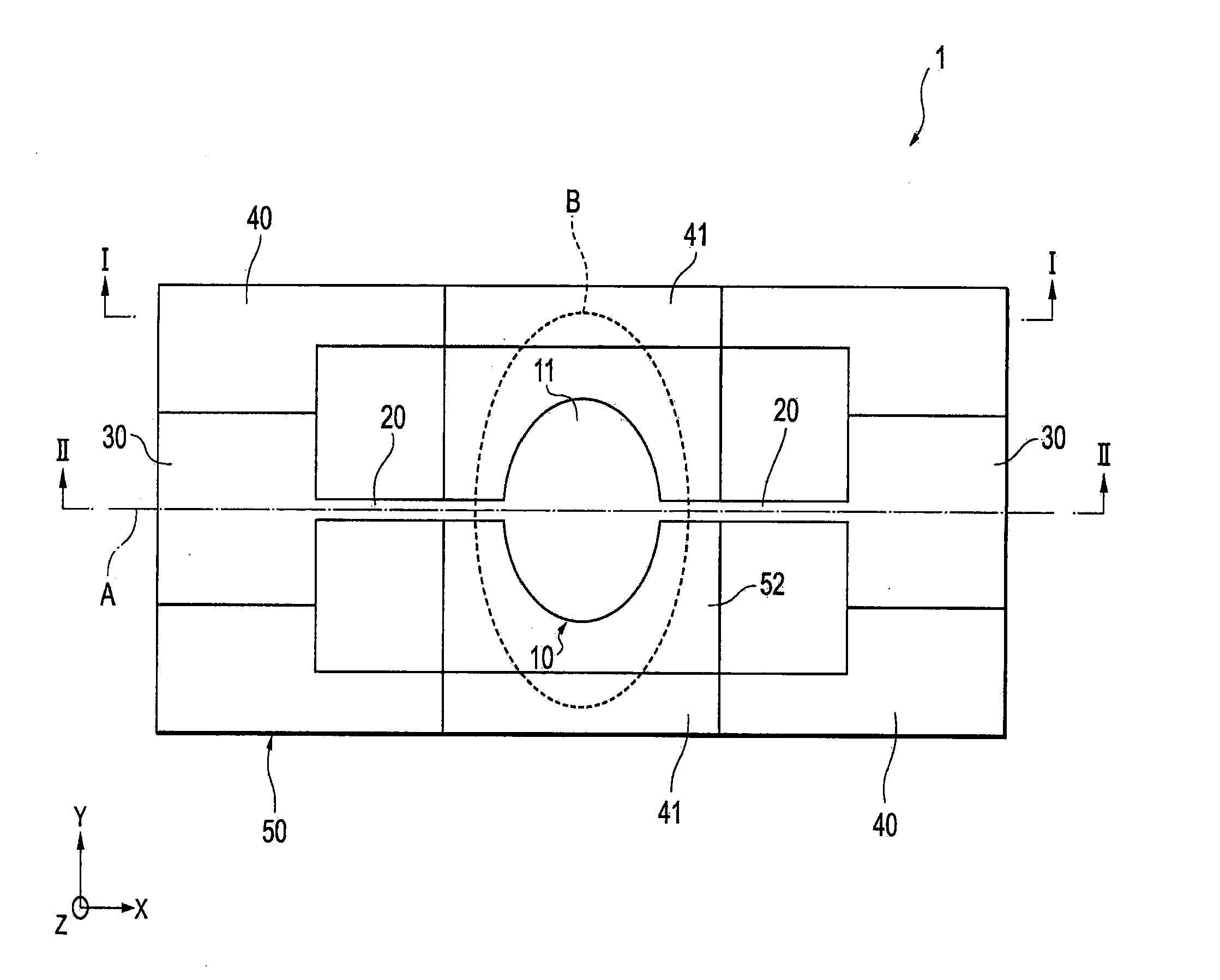
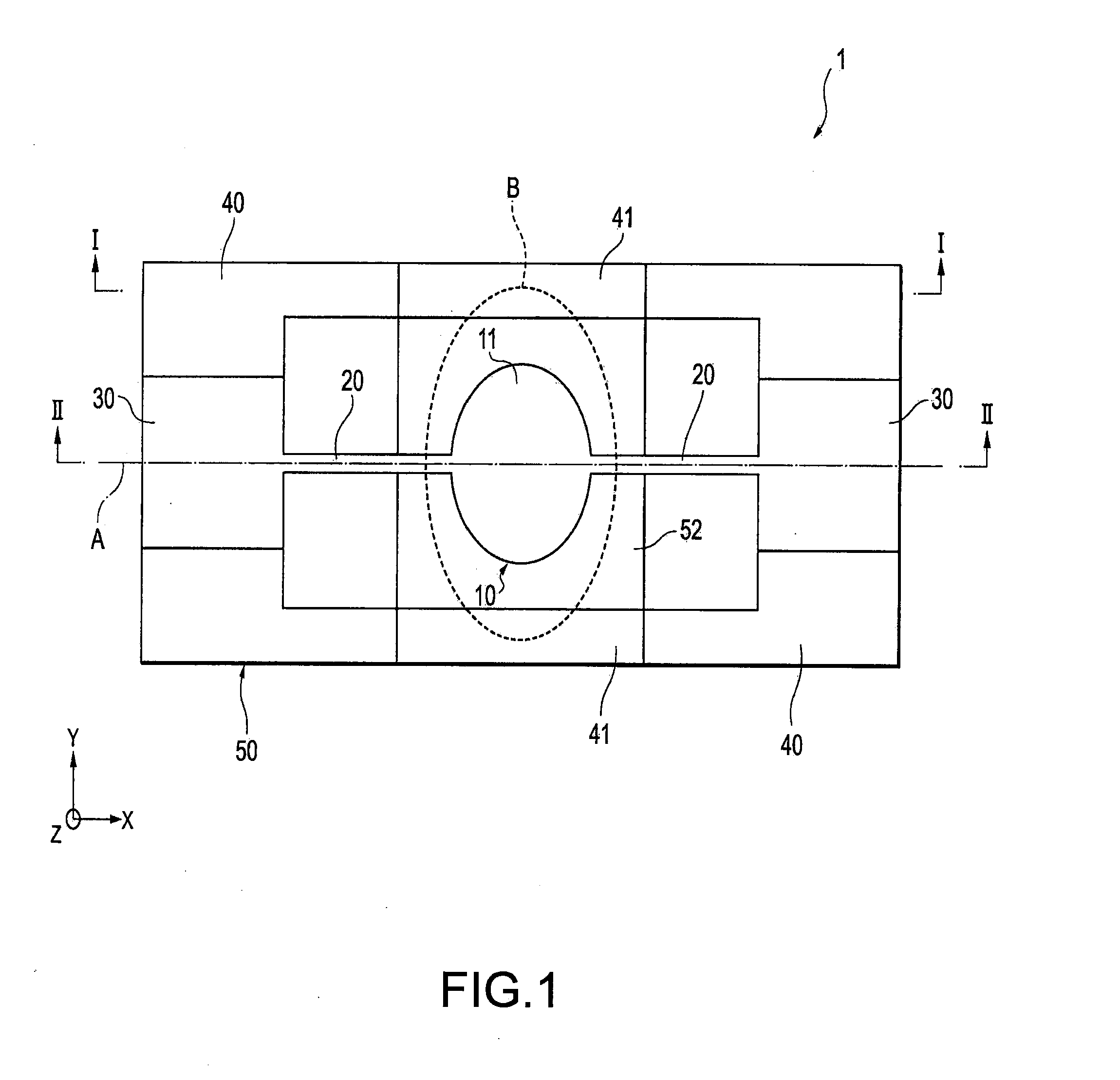
[0031]FIGS. 1 to 4 show an optical device according to an embodiment of the invention, and FIG. 1 is a plan view describing the configuration of the optical device according to the embodiment of the invention.

[0032]As shown in FIG. 1, an optical device 1 includes a movable plate 10, a pair of axis members 20, a securing portion 30, a frame 40, and a support member (holder) 50. An external light source (not shown) emits light that spreads in a normal distribution (Gauss distribution or Gaussian distribution), and the light is then incident on the optical device 1. The light is spread over the area B shown in FIG. 1.

[0033]A metal film 11 is formed on the upper surface (one surface) of the movable plate 10, and the movable plate 10 is disposed in the area B over which light is spread and reflects the light. The metal film 11 corresponds to the light reflecting surface in an embodimen...


PUM


Abstract

An optical device includes: a movable plate disposed in an area over which externally incident light is spread, the movable plate having a light reflecting surface that reflects the light; and an axis member that swingably supports the movable plate around a predetermined axis, wherein each portion in the light spread area but other than the movable plate is formed of a surface having a normal vector along which the light is reflected and directed outside a predetermined area.

Description

[0001]The entire disclosure of Japanese Patent Application No: 2009-075919, filed Mar. 26, 2009 is expressly incorporated by reference herein.BACKGROUND[0002]1. Technical Field[0003]Some aspects according to the present invention relate to an optical device, an optical scanner, and an image forming apparatus produced, for example, by using a MEMS (Micro Electro Mechanical System) technology and having a movable plate making reciprocating motion around an axis member.[0004]2. Related Art[0005]An optical device of this type that has been known in the related art includes a magnetic field generator and a scan mirror. Both ends of the scan mirror are supported by a support member in such a way that the scan mirror can be angularly displaced around a drive axis. The scan mirror has a mirror portion formed on one side and a permanent magnet formed on the other side. The magnetic field generator is disposed on the other side of the scan mirror and apart therefrom by a predetermined distanc...

Claims


Application Information

Patent Timeline
IPC IPC(8): G02B26/10G02B26/08
CPCG02B27/141G02B26/105
Inventor MIZOGUCHI, YASUSHINAKAMURA, MAKIKO
Owner SEIKO EPSON CORP
Why Eureka
Try Eureka