Method and apparatus of microwave photonics signal processing

a microwave photonics and signal processing technology, applied in the field of radiofrequency signal processing, can solve the problems of often encountered trade-offs by practitioners, and achieve the effect of high bandwidth operation

Inactive Publication Date: 2010-09-30
ALCATEL-LUCENT USA INC
View PDF6 Cites 2 Cited by
  • Summary
  • Abstract
  • Description
  • Claims
  • Application Information

AI Technical Summary

Benefits of technology

[0004]We have developed a radiofrequency (rf) signal-processing device that offers the possibility of high bandwidth operation. Our new device applies principles of microwave photonics and Linear Amplification based on Nonlinear Components (LINC). For some applications, accordingly, our invention may be embodied in an rf amplifier or rf transmitter.

Problems solved by technology

In designing or selecting signal processing devices for particular rf applications, practitioners often encounter tradeoffs among factors such as bandwidth, efficiency, linearity, and cost.
Such tradeoffs are encountered, for example, when designing or selecting power amplifiers for use in wireless communication systems.

Method used


Image

  • Method and apparatus of microwave photonics signal processing
  • Method and apparatus of microwave photonics signal processing
  • Method and apparatus of microwave photonics signal processing

Examples


Embodiment Construction

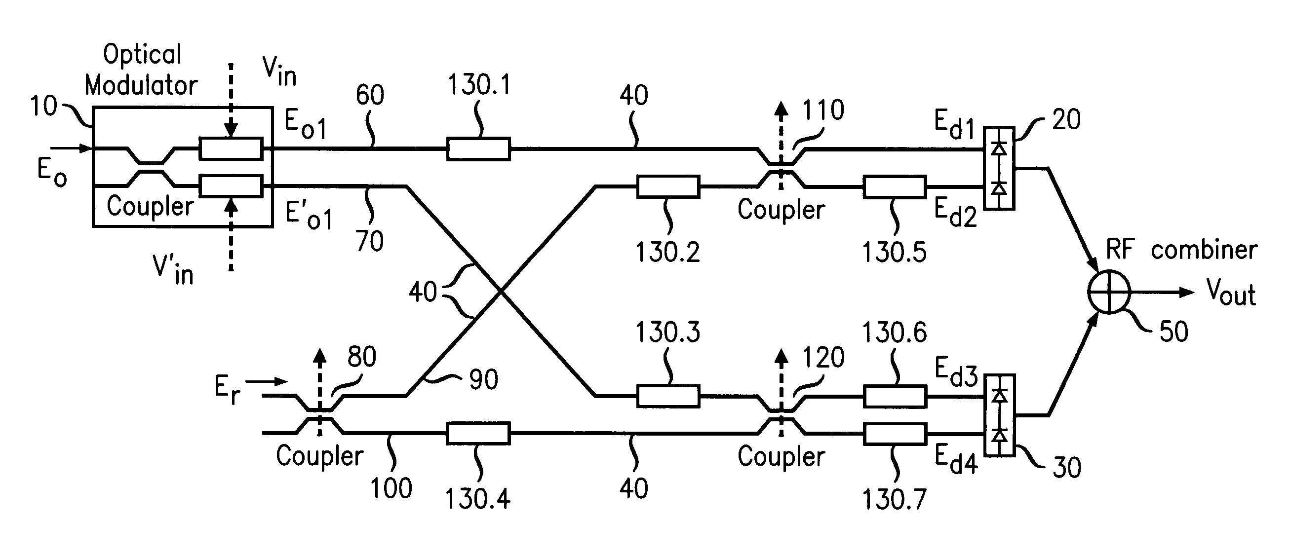
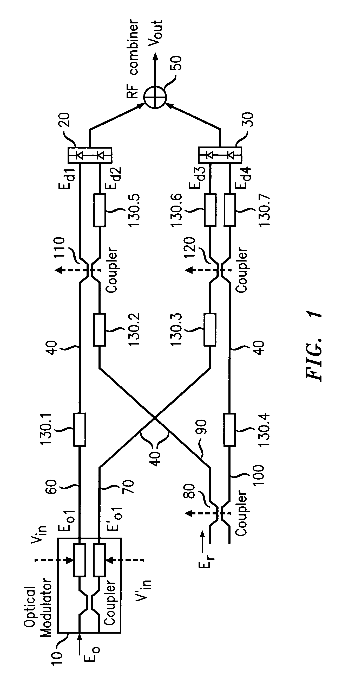
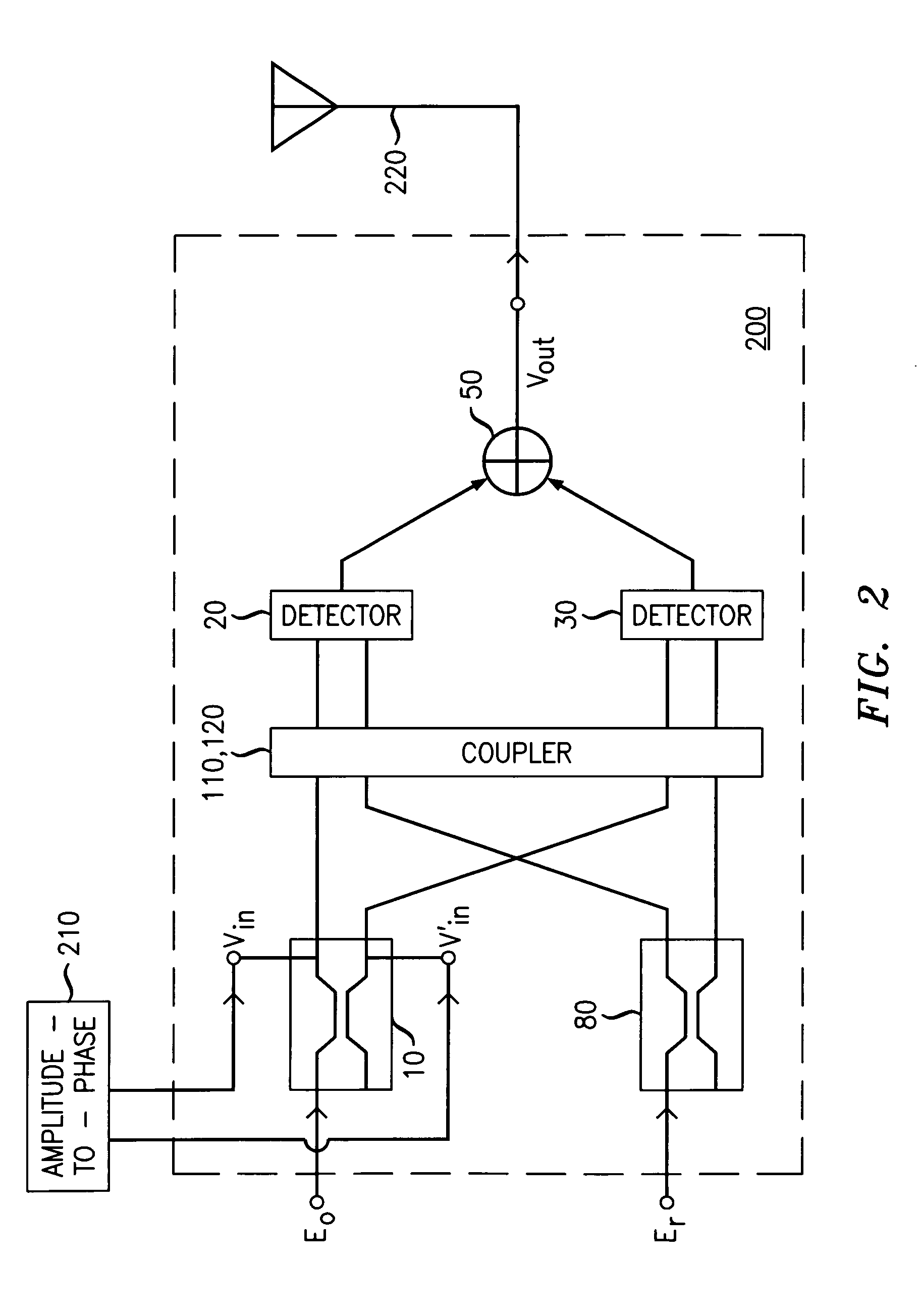
[0013]The principles of LINC are known. Consider a carrier frequency ω and a time-varying signal a(t) which varies slowly relative to cos(ωt+θ), where θ is an arbitrary phase angle. Let Amax be the magnitude of the maximum positive or negative excursion of a(t); i.e., Amax=max|a(t)|. The phase function φ(t) is constructed from a(t) according to the transformation,

12φ(t)=cos-1(a(t)Amax).

[0014]A simple trigonometric identity can now be invoked to show that the amplitude-modulated signal a(t)cos(ωt+θ) can be expressed as the sum of two constant-amplitude, phase-modulated signals; i.e.,

a(t)cos(ωt+θ)=Amax2cos(ωt+θ+12φ(t))+Amax2cos(ωt+θ-12φ(t)).

[0015]Those skilled in the art of power amplification for wireless communication, among others, have recognized that tradeoffs exist among efficiency, linearity, and bandwidth. In particular, the conventional amplification of amplitude-modulated signals having large peak-to-average power ratios may test the limits of favorable tradeoffs among those...


PUM


Abstract

A radiofrequency (rf) signal-processing device offers the possibility of high bandwidth operation. The disclosed device applies principles of microwave photonics and Linear Amplification based on Nonlinear Components (LINC). For some applications, the device may be embodied in an rf amplifier or rf transmitter. In an embodiment, an optical phase modulator is configured to receive an optical carrier signal as input, and further configured so that, when driven by an rf modulation signal, it will produce a complementary pair of optical signals as output. Each of a pair of detectors is configured to convert a respective one of the complementary optical signals to an rf signal. An rf combiner is configured to add the converted radiofrequency signals from the detectors to form an output signal.

Description

FIELD OF THE INVENTION[0001]The invention relates to processing of radiofrequency signals.ART BACKGROUND[0002]Devices for processing radiofrequency (rf) signals are essential for telecommunications and other applications. In designing or selecting signal processing devices for particular rf applications, practitioners often encounter tradeoffs among factors such as bandwidth, efficiency, linearity, and cost. Such tradeoffs are encountered, for example, when designing or selecting power amplifiers for use in wireless communication systems.[0003]As the demands on wireless networks, for example, continue to increase, there is a growing need for equipment that achieves favorable balances among these factors. For this reason, among others, there is a need for new rf signal-processing hardware that achieves improvements in at least some of these factors.SUMMARY OF THE INVENTION[0004]We have developed a radiofrequency (rf) signal-processing device that offers the possibility of high bandwi...

Claims


Application Information

Patent Timeline
Patent Type & Authority Applications(United States)
IPC IPC(8): H04B10/00
CPCH03F1/0294
Inventor CHEN, YOUNG-KAITU, KUN-YIIZIERDT, MICHAEL GEORGE
Owner ALCATEL-LUCENT USA INC
Why Eureka
Try Eureka