High-frequency RMS-DC converter using chopper-stabilized square cells

a chopper-stabilized, square cell technology, applied in the direction of power measurement by using square-law characteristics, electric/magnetic computing, instruments, etc., can solve the problems of reducing the maximum operating frequency of the rms power detector, reducing the maximum operating frequency, and not scaling well, so as to reduce the required device size, and eliminate the effect of offs

Active Publication Date: 2014-08-21
ANALOG DEVICES INT UNLTD
View PDF3 Cites 3 Cited by
  • Summary
  • Abstract
  • Description
  • Claims
  • Application Information

AI Technical Summary

Benefits of technology

[0017]The present invention provides an RMS-DC converter architecture that uses chopping around—intrinsically high-bandwidth—square cells to eliminate offset, thus enabling high-bandwidth operation because (a) only a small portion of the circuitry (i.e., a single square cell) operates at high frequencies; (b) high-bandwidth square cells may be used; and (c) chopping minimizes the required device size to achieve an acceptable square cell dynamic range, thereby maximizing the square cell bandwidth. In addition, an RMS-DC converter according to the present invention consumes less power than conventional RMS converter of the prior art that requires a high-frequency variable gain amplifier.
[0018]In accordance with one embodiment of the present invention, an RMS to DC converter applies chopping to a combination of two square cells so as to eliminate DC offset from the square cells' output signals. The RMS to DC converter of the present invention may include a first input switch for receiving an input signal supplied to the RMS to DC converter, and transferring the input signal alternatively to a first square cell or to a second square cell, but not to both simultaneously. A second input switch may receive a reference signal and transfer it alternately to the second square cell or to the first square cell, but not to both simultaneously. The first and second input switches are controlled so as to provide the first square cell with the input signal, when the second square cell is supplied with the reference signal, and to supply the first square cell with the reference signal, when the second square cell is provided with the input signal. A subtraction operation may be performed to provide a difference signal representing a difference between the output signals of the first and second square cells. The output signals may be filtered either before or after the subtraction operation, or both, to eliminate high-frequency components.
[0020]In accordance with another embodiment of the present invention, the reference signal may be a DC signal, e.g. zero. The reference signal may also be a wave-shaped signal, and the chopped square cell determines the difference between the average power levels of the input signal and the reference signal.
[0022]In accordance with one embodiment of the present invention, the switch control signal (i.e. the chopper signal) may have a frequency that is less than the lowest frequency of the input signal. The frequency of the switch control signal may also be lower than the bandwidth of the input signal, (i.e. lower than the difference between the highest and the lowest frequencies of the input signal). The conversion technique of the present invention may improve performance of an RMS to DC converter by extending the dynamic range of the RMS to DC converter at a given operating frequency. Alternatively, the conversion technique of the present invention may extend useable operating frequency range of an RMS to DC converter while maintaining an acceptable dynamic range.
[0023]Offset chopping may be applied to a square cell, thereby enhancing the useful dynamic range for a given transistor size.

Problems solved by technology

One design challenge for RMS power detectors is to provide a sufficient dynamic range at high input frequencies, as measured by, for example, a ratio of the largest input power level to the smallest input power level that can be accurately detected.
Although most square cells have a high bandwidth, most have a poor dynamic range because of DC offsets resulting from device mismatches.
However, such dynamic range enhancement techniques often significantly reduce the maximum operating frequency of the RMS power detector.
The maximum operating frequency does not scale well with the transition or cut-off frequency (fT) of a bipolar device, which is used in practically all RF RMS power detectors.
The dynamic range of an RMS power detector is primarily limited by the DC offset resulting from mismatches between the bipolar or MOS devices used in the RMS power detector.
The bandwidth of an RMS power detector is generally large, limited by junction capacitances, together with the impedance of the voltage source driving the cell.
Enlarging the devices, though a proven technique to reduce the effects of device offsets, is not effective in enhancing the dynamic range of a square cell.
Trimming, however, cannot remove all offset components from the square cell output signal (see, e.g., Kouwenhoven).
Especially over the full operating temperature range the effectiveness of trimming is limited.
However, device scaling cannot achieve both high bandwidth and a sufficiently wide dynamic range.
Numerous circuit techniques may be used to increase the dynamic range of a square cell that is suitable for use in a high dynamic range RMS-DC converter, although most of these techniques limit the attainable RMS detector bandwidth.
The disadvantages of such an approach includes (a) the effect of an offset generated inside the square cell on the dynamic range of the RMS power detector is not mitigated (i.e., to achieve a reasonable dynamic range, large devices and offset trimming are still required); (b) the attainable bandwidth is still significantly limited by the required large device sizes; and (c) temperature drift and frequency dependence of the square cell transfer function are directly observable in the overall detector transfer function.
RMS power detector also has an disadvantage that, as VGA 102 processes RF input signal 101, VGA 102 requires a large bandwidth over the full VGA gain range (e.g., at least equal to the required detector dynamic range in dB).
Another disadvantage of RMS power detector 100 is that its attainable bandwidth is primarily limited by the bandwidth of the VGA.
The disadvantages of RMS power detector 200 includes (a) requiring both large device sizes and trimming of the square cells to achieve a reasonable dynamic range, thereby undesirably reducing the attainable bandwidth; (b) the feedback loop typically results in a slow detector response (i.e., a lengthy response time), and (c) potential instability since the loop gain varies significantly as a function of the input power level applied to the detector.
A multiplier-based square cell, however, has a considerably lower bandwidth than other square cells and is therefore less suited to realize an RMS-DC converter at very high frequencies.
Also, a multiplier-based square cell operates at much higher current densities and results in higher overall power consumption.

Method used


Image

  • High-frequency RMS-DC converter using chopper-stabilized square cells
  • High-frequency RMS-DC converter using chopper-stabilized square cells
  • High-frequency RMS-DC converter using chopper-stabilized square cells

Examples


Embodiment Construction

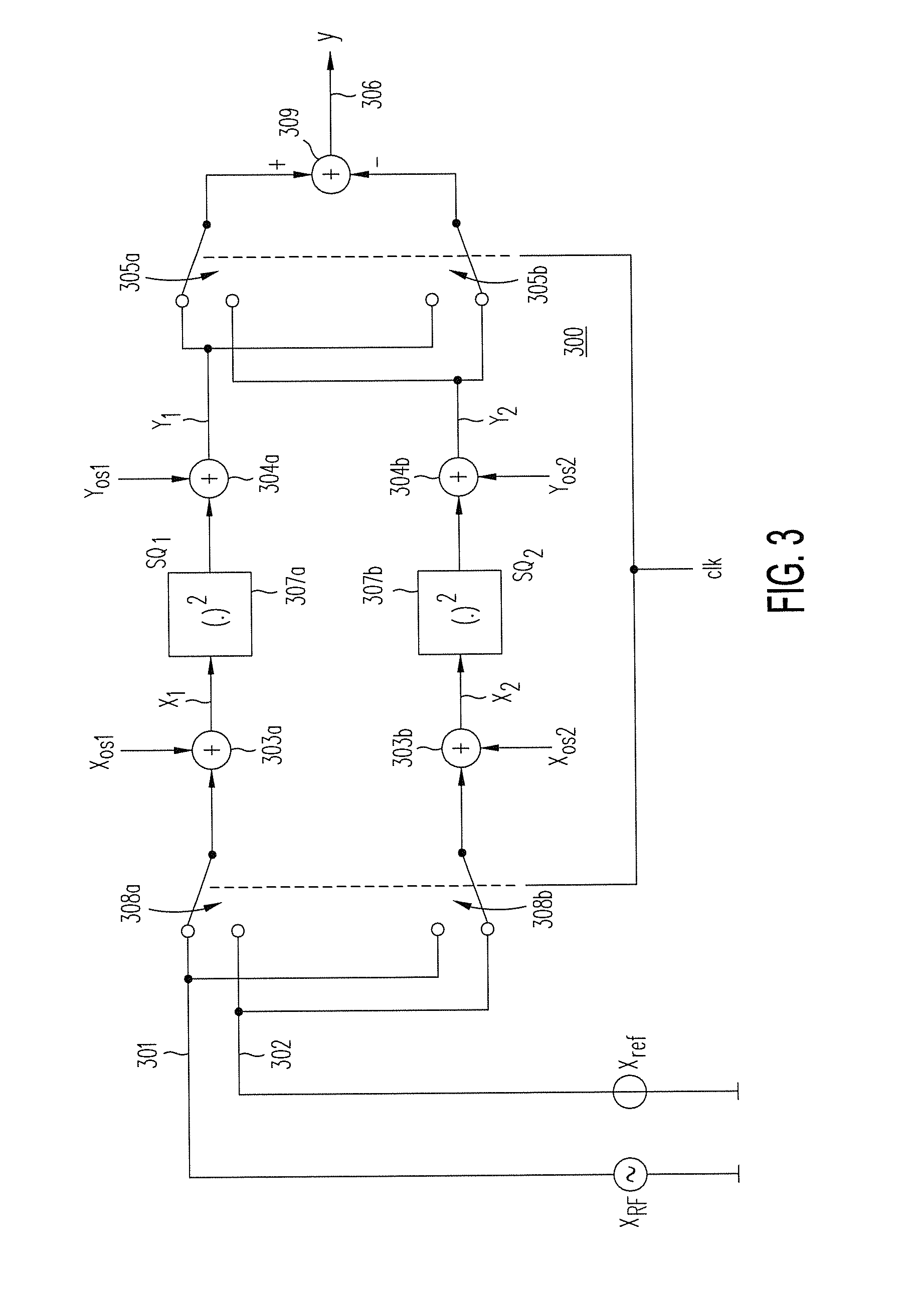
[0042]FIG. 3 illustrates chopper-stabilized square cell 300, in accordance with one embodiment of the present invention. As shown in FIG. 3, chopper-stabilized square cell 300 includes input signal 301 and reference signal 302, which are each selectively provided by either switches 308a or 308b to square cell 307a or square cell 307b, depending on the state of switches 308a and 308b. At any given time, if switch 308a is set to receive input signal 301, switch 308b is set to receive reference signal 302. Alternatively, if switch 308a is set to receive reference signal 302, switch 308b is set to receive input signal 301. As each square cell has internal offsets that add to either the input signal or the output signal, these offsets are represented by adders 303a and 303b that add offsets XOS1 and XOS2 to the signals provided to square cells 307a and 307b, respectively, and adders 304a and 304b that add offsets YOS1 and YOS2 to the output signals of square cells 307a and 307b, respecti...


PUM


Abstract

An RMS-DC converter includes a chopper-stabilized square cell that eliminates offset, thus enabling high-bandwidth operation. The chopper-stabilized offset requires only a small portion of the circuitry (i.e., a single component square cell) which operates at high frequencies, and is amenable to using high-bandwidth component square cells. Using the chopping technique minimizes required device sizes without compromising an acceptable square cell dynamic range, thereby maximizing the square cell bandwidth. The RMS-DC converter consumes less power than conventional RMS-to-DC converters that requires a high-frequency variable gain amplifier.

Description

CROSS REFERENCE TO RELATED APPLICATIONS[0001]The present application relates to and claims priority of U.S. provisional patent application (“Co-pending Provisional Patent Application”), Ser. No. 61 / 767,628, entitled “High-Frequency RMS-DC Converter Using Chopper-Stabilized Square Cells,” filed on Feb. 21, 2013. The disclosure of the copending Provisional Patent Application is hereby incorporated by reference in its entirety.BACKGROUND OF THE INVENTION[0002]1. Field of the Invention[0003]The present invention relates to radio transmitter systems. More particularly, the present invention relates to Root-Mean-Square (RMS) to DC converters, also called “RMS power detectors.”[0004]2. Discussion of the Related Art[0005]RMS power detectors typically operate within a dynamic range at a wide range of radio frequencies, thus RMS power detectors are found in numerous kinds of communication and instrumentation equipment, with special application in accurate measurements of average power levels ...

Claims


Application Information

Patent Timeline
Patent Type & Authority Applications(United States)
IPC IPC(8): H02M7/217G06G7/20
CPCG06G7/20H02M7/217G01R19/02G01R21/10
Inventor KOUWENHOVEN, MICHAEL HENDRIKUS LAURENTIUS
Owner ANALOG DEVICES INT UNLTD
Why Eureka
Try Eureka