Sheet Metal Panel Shape for Low Sound Radiation

a sheet metal panel and low sound radiation technology, applied in the direction of transportation and packaging, mechanical equipment, layered products, etc., can solve the problems of vibrational energy of sheet metal panels and sound emission from body panels, and achieve the effect of reducing or eliminating, reducing sound radiation, and reducing sound radiation

Inactive Publication Date: 2010-09-30
GM GLOBAL TECH OPERATIONS LLC
View PDF21 Cites 2 Cited by
  • Summary
  • Abstract
  • Description
  • Claims
  • Application Information

AI Technical Summary

Benefits of technology

[0004]A shape for sheet metal stampings is provided that will minimize the radiation of sound from the panel, to thereby reduce or eliminate the need to add supplemental acoustical absorbing or barrier materials. The sheet metal panel shape includes a crown portion, a peripheral flange that extends around the boundary of the crown portion, a flat portion that truncates the crown, and a bead pattern that is formed in at least the flat portion of the panel, whereby the crown and the flat and the bead pattern cooperate to define a panel shape that has low sound radiation. The bead pattern can also extend part way or more into the crown portion.

Problems solved by technology

When the vehicle is driven, these sheet metal panels are subjected to vibrational energy from the engine and from the highway surface.
The vibration of panels in this way is especially critical in the large flat panels used in the vehicle floor, including the luggage compartment and in the foot wells.
Because the radiated sound is objectionable, it is well known to install acoustic materials that will dampen the vibration and thereby reduce the emission of sound from the body panels.

Method used


Image

  • Sheet Metal Panel Shape for Low Sound Radiation
  • Sheet Metal Panel Shape for Low Sound Radiation
  • Sheet Metal Panel Shape for Low Sound Radiation

Examples


Embodiment Construction

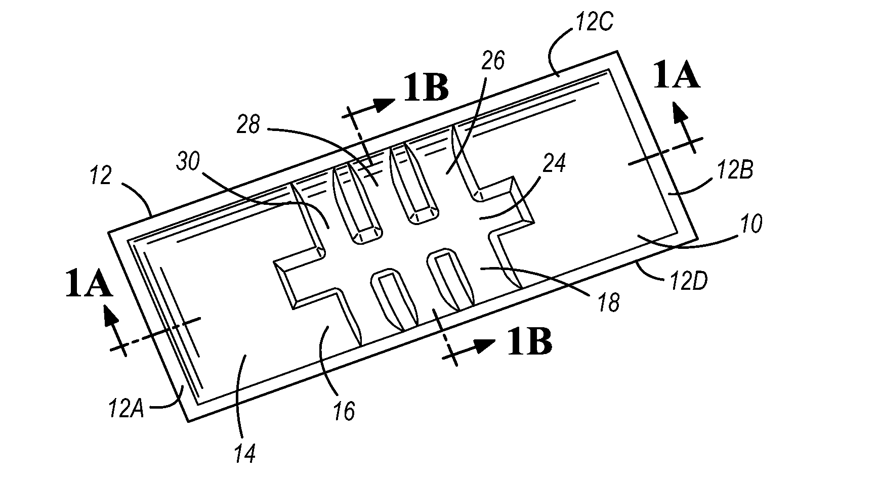
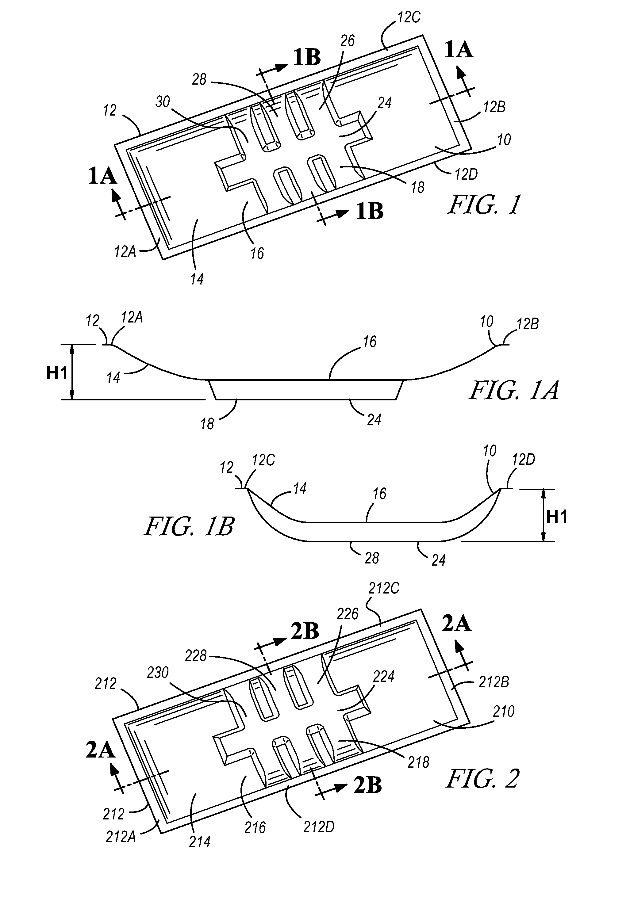
[0029]Referring to FIGS. 1, 1A, and 1B, it is seen that a sheet metal panel 10 is provided and includes a peripheral flange 12, a crown 14, a flat 16 and a bead pattern 18. The flange 12 defines the outer edge of the panel 10 and generally bounds the four sides of the crown 14. Panel 10 is shown to be generally rectangular in shape and thus the flange 12 can be seen to include end flanges 12A and 12B and side flanges 12C and 12D. The flange 12 enables the panel 10 to be welded to adjacent panels, or the panel 10 can be integral with the adjacent panels and stamped in one piece therewith. As seen in FIGS. 1A and 1B, the flange 12 is preferably in a single plane. Sheet metal panel 10 is made in a sheet metal stamping process in which the panel 10 is shaped between an upper die and a lower die which form the shape of the panel 10 including the flange 12, crown 14, flat 16 and the bead pattern 18.

[0030]As best seen in FIGS. 1A and 1B, the crown 14 is a curvilinear or bulged shape that e...


PUM

PropertyMeasurementUnit
heightaaaaaaaaaa
vibrational energyaaaaaaaaaa
shapeaaaaaaaaaa

Abstract

A shape for sheet metal stampings is provided that will minimize the radiation of sound from the panel, to thereby reduce or eliminate the need to add supplemental acoustical absorbing or barrier materials. The sheet metal panel shape includes a crown portion, a peripheral flange that extends around the boundary of the crown portion, a flat portion that truncates the crown, and a bead pattern that is formed in at least the flat portion of the panel, whereby the crown and the flat and the bead pattern cooperate to define a panel shape that has low sound radiation. The bead pattern can also extend part way or more into the crown portion.

Description

FIELD OF THE INVENTION[0001]The present invention relates to the shaping of a sheet metal panel to minimize noise emission and more particularly provides a sheet metal panel having a combination of a flange, a crown, a flat and a bead to reduce sound radiation while it is exposed to vibration.BACKGROUND OF THE INVENTION[0002]It is well known to construct a motor vehicle body by welding together a number of sheet metal panels. When the vehicle is driven, these sheet metal panels are subjected to vibrational energy from the engine and from the highway surface. This vibrational energy is transmitted into sound radiations as the panels vibrate. The vibration of panels in this way is especially critical in the large flat panels used in the vehicle floor, including the luggage compartment and in the foot wells. Because the radiated sound is objectionable, it is well known to install acoustic materials that will dampen the vibration and thereby reduce the emission of sound from the body pa...

Claims


Application Information

Patent Timeline
Patent Type & Authority Applications(United States)
IPC IPC(8): B21C37/02
CPCB60R13/08Y10T428/12201B60R13/083
Inventor WANG, CHONGREILLY, SCOTT M.ROGGENKAMP, TIMOTHY J.
Owner GM GLOBAL TECH OPERATIONS LLC
Why Eureka
Try Eureka