

Cell separating apparatus and cell separating method
a cell separation and cell technology, applied in the field of cancer cell separation apparatus and cancer cell separation method, can solve the problem of insufficient effect and achieve the effect of reliably separating cancer cells
- Summary
- Abstract
- Description
- Claims
- Application Information
AI Technical Summary
Benefits of technology
Problems solved by technology
Method used
Image

Examples
first embodiment
1. First Embodiment
1.1. Configuration of Cancer Cell Separating Apparatus and Cancer Cell Separating Method
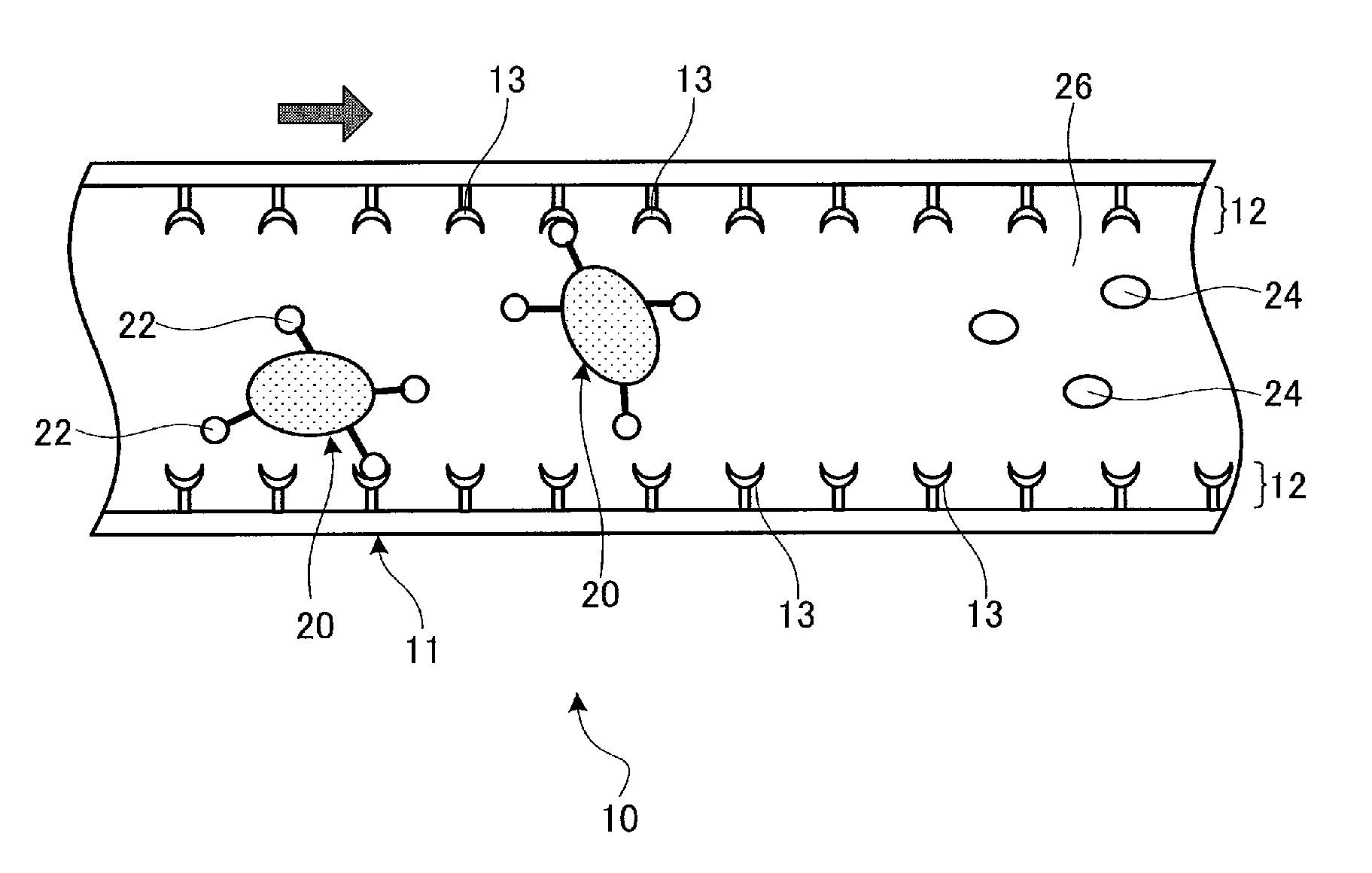
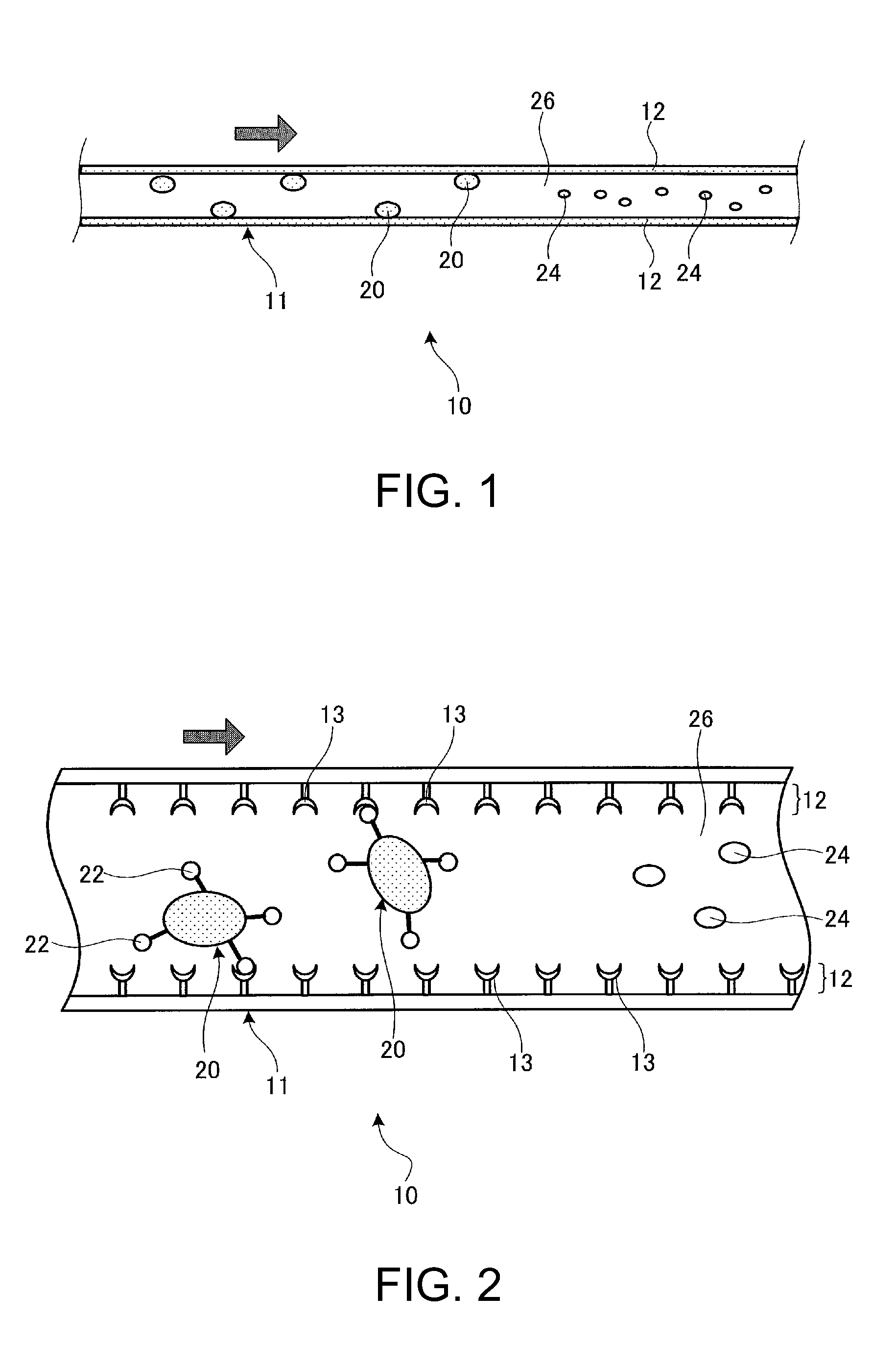
[0032]FIG. 1 is a cross-sectional view diagrammatically showing a cancer cell separating apparatus 10 according to a first embodiment of the invention and FIG. 2 is an enlarged cross-sectional view of the cancer cell separating apparatus 10 shown in FIG. 1 for explaining a cancer cell separating method with the cancer cell separating apparatus 10.
[0033]The cancer cell separating apparatus 10 according to the first embodiment has a function to selectively separate cancer cells 20 from non-cancer cells (cells other than cancer cells) 24 in a cell slurry 26. In this specification, the term “cancer cells” means malignant tumor cells. The cell slurry 26 is liquid including at least cells and is liquid which may include cancer cells and, for example, is liquid including the cancer cells and non-cancer cells. As the cell slurry 26, body fluids such as blood, lymph fluid, salivarius, u...
second embodiment
2. Second Embodiment
2.1. Configuration of Cancer Cell Separating Apparatus and Method of Usage
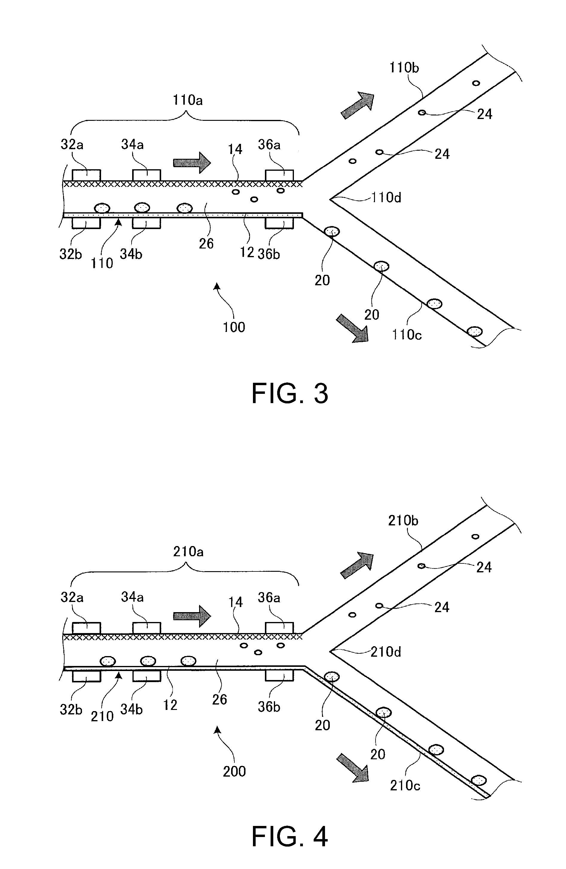
[0045]FIG. 3 is a drawing diagrammatically showing a cross section of a cancer cell separating apparatus 100 according to the second embodiment.
[0046]The cancer cell separating apparatus 100 according to the second embodiment is different in configuration from the cancer cell separating apparatus 10 according to the first embodiment in that (i) a flow channel 110 includes a first portion 110a, and a second portion 110b and a third portion 110c bifurcated from an one end portion of the first portion 110a, and in that (ii) a first electrode pair 32a and 32b, a second electrode pair 34a and 34b, and a dielectric migration electrode pair 36a and 36b are provided respectively so as to interpose the flow channel 110.
[0047]The cancer cell separating apparatus 100 according to the second embodiment is configured to separate the cancer cells 20 from the non-cancer cells 24 using a difference in velo...
third embodiment
3. Third Embodiment
3.3. Configuration of Cancer Cell Separating Apparatus and Method of Usage
[0059]FIG. 4 is a drawing diagrammatically showing a cross section of a cancer cell separating apparatus 200 according to a third embodiment.
[0060]The cancer cell separating apparatus 200 according to the third embodiment is different from the cancer cell separating apparatus 100 according to the second embodiment in that the antibody fixation area 12 is provided also on a third portion 210c of a flow channel 210, but has the same configuration as the cancer cell separating apparatus 100 according to the second embodiment other than the above-described point. Therefore, the cancer cell separating apparatus 200 according to the third embodiment achieves the same effects and advantages as the cancer cell separating apparatus 100 according to the second embodiment. The method of using the cancer cell separating apparatus 200 according to the third embodiment is the same as that of the cancer ce...
PUM
| Property | Measurement | Unit |
|---|---|---|
| velocity | aaaaa | aaaaa |
| fixation area | aaaaa | aaaaa |
| time lengths | aaaaa | aaaaa |
Abstract
Description
Claims
Application Information