Ultrasonic transducer

a transducer and ultrasonic technology, applied in the field of ultrasonic transducers, can solve the problems of difficult and complicated treatment of tumors with relatively large volumes, limited range of movement range of ultrasonic transducers, and limited treatment range of tumors, so as to reduce treatment time, increase treatment efficiency, and increase the range of ultrasonic therapy

Inactive Publication Date: 2010-09-30
SIEMENS AG
View PDF3 Cites 3 Cited by
  • Summary
  • Abstract
  • Description
  • Claims
  • Application Information

AI Technical Summary

Benefits of technology

[0021]Because the transducer units of the ultrasonic transducer in the present invention are divided into a number of sets, with the transducer units in each set having the same focus position while the transducer units in different sets have different focus positions, and the focus points are distributed in a relatively large spatial range, the range of ultrasonic therapy can be increased even within the narrow and limited space of the magnetic resonance imaging equipment. A number of sets of transducer units can simultaneously output power to carry out treatment at different locations, so that the treatment efficiency is increased and the treatment time is reduced. Since the ultrasonic transducer in the present invention can heat a relatively large space range, the therapeutic schemes for a large tumor can be simplified, and the overall treatment of the tumor can be completed by positioning the patient once. The present invention is not limited to use in the HIFU equipment monitored by magnetic resonance; it is also applicable to other HIFU equipment with a narrow mechanical space.

Problems solved by technology

Since the field of view (examination volume) of the magnetic resonance imaging equipment is usually relatively narrow, the movement range of the ultrasonic transducer is made to be very limited.
For a tumor with a relatively large volume to be treated, it is very difficult to carry out the thermal therapy for the whole volume to be treated only by moving the ultrasonic transducer, which makes the treatment of the tumor with a relatively large volume complicated and difficult.
However, in order to ensure the appropriate form of the focus of the ultrasonic transducer, the focal length can only be changed within a very limited range.
In other words, the method is very limited in increasing the therapeutic range.
However, in the multiple ultrasonic focus points produced by the acoustic lens, the ultrasound output at each ultrasonic focus point cannot be controlled independently.
Since in this method it is necessary to reposition the patient, the time for treatment and the complexity of the treatment are increased.

Method used


Image

  • Ultrasonic transducer
  • Ultrasonic transducer
  • Ultrasonic transducer

Examples


Embodiment Construction

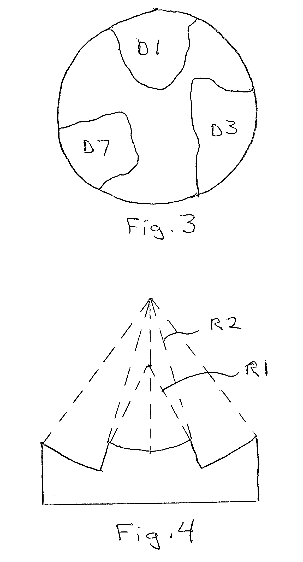
[0030]The geometric shape of a conventional single-focus ultrasonic transducer is a concave spherical surface, with the center of the sphere being the geometric focus of the ultrasonic transducer, and the curvature radius of the sphere being the focus length. The ultrasonic transducer proposed in the present invention is not limited to a concave spherical shape, instead it can be of an arbitrary shape. However, for the easy description of the technical solution of the present invention, a concave spherical shape will be taken mainly as an example in the following description.

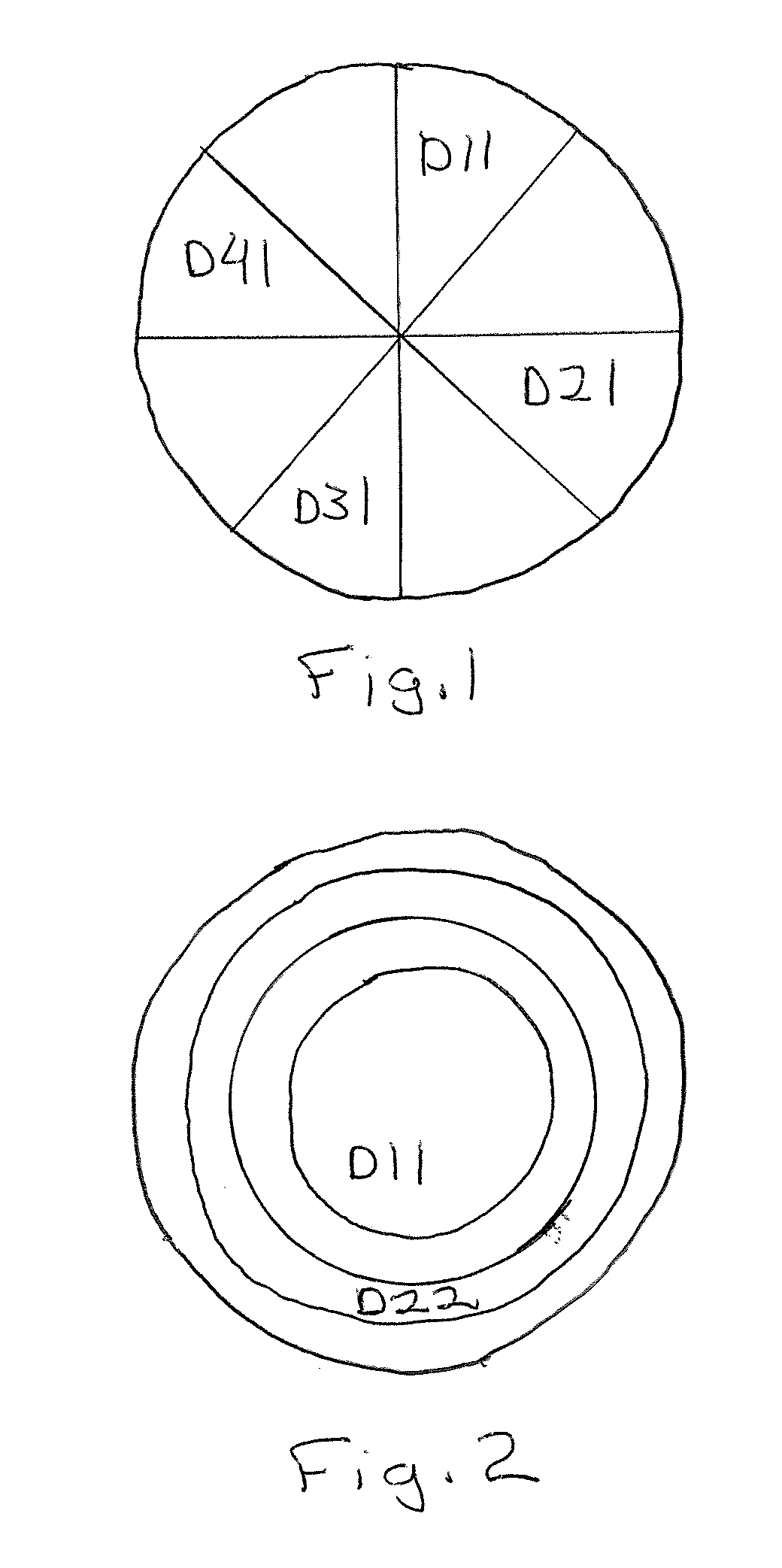
[0031]In an embodiment of the present invention, an ultrasonic transducer is divided into n (n≧2) sets of transducer units, with all the sets of transducer units being designed with a concave spherical surface, and the transducer units in the same set having the same focus position, and the transducer units in different sets having different focus positions. For convenience, the sets of transducer units are desi...


PUM


Abstract

An ultrasonic transducer has at least two sets of transducer units, with all the transducer units in each set having the same focus position and the transducer units in the different sets having different focus positions. Since the focus points of the sets of ultrasonic transducer units are distributed in a relatively large spatial range, the range of ultrasonic therapy can be increased even within the narrow and limited space of magnetic resonance imaging equipment.

Description

BACKGROUND OF THE INVENTION[0001]1. Field of the Invention[0002]The present invention relates to the field of ultrasonic transducers and, particularly, to a multi-focus ultrasonic transducer.[0003]2. Description of the Prior Art[0004]In treatment of a patient with high-intensity focused ultrasound (HIFU) monitored by magnetic resonance imaging (MRI), magnetic resonance imaging equipment can be used to measure the temperature of the heated area of HIFU equipment and to monitor the anatomical image. The focus of the ultrasonic transducer can be made to cover a certain volume of the therapeutic area by the mechanical three-dimension movement of the ultrasonic transducer (treatment head). Since the field of view (examination volume) of the magnetic resonance imaging equipment is usually relatively narrow, the movement range of the ultrasonic transducer is made to be very limited. For a tumor with a relatively large volume to be treated, it is very difficult to carry out the thermal ther...

Claims


Application Information

Patent Timeline
Patent Type & Authority Applications(United States)
IPC IPC(8): A61N7/00
CPCA61B2017/00084A61B2019/5236A61N2007/0078A61N2007/0056A61N7/02A61B2090/374
Inventor ZHOU, XIAO DONGSTEINMEYER, FLORIANNI, CHENG
Owner SIEMENS AG
Why Eureka
Try Eureka