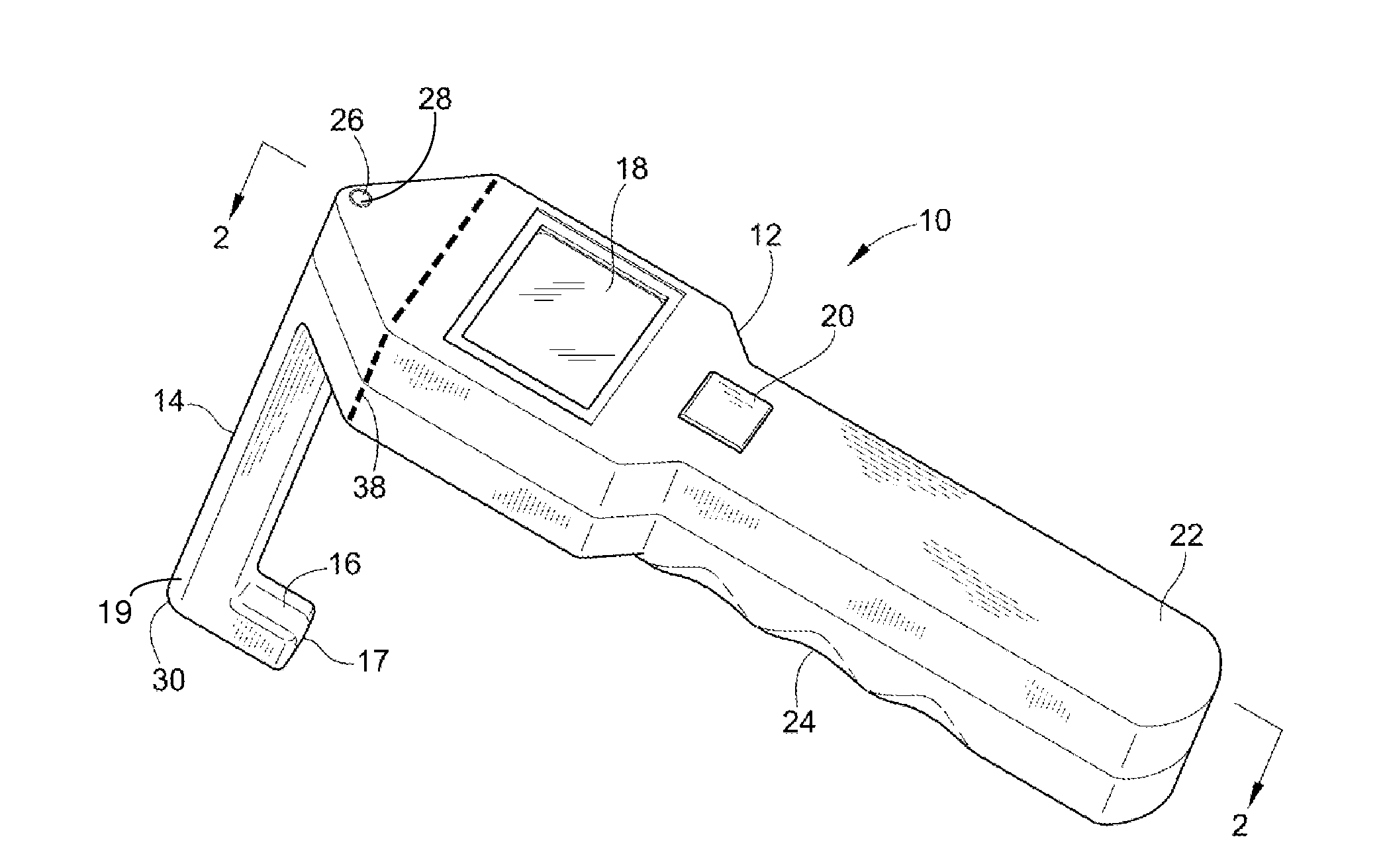
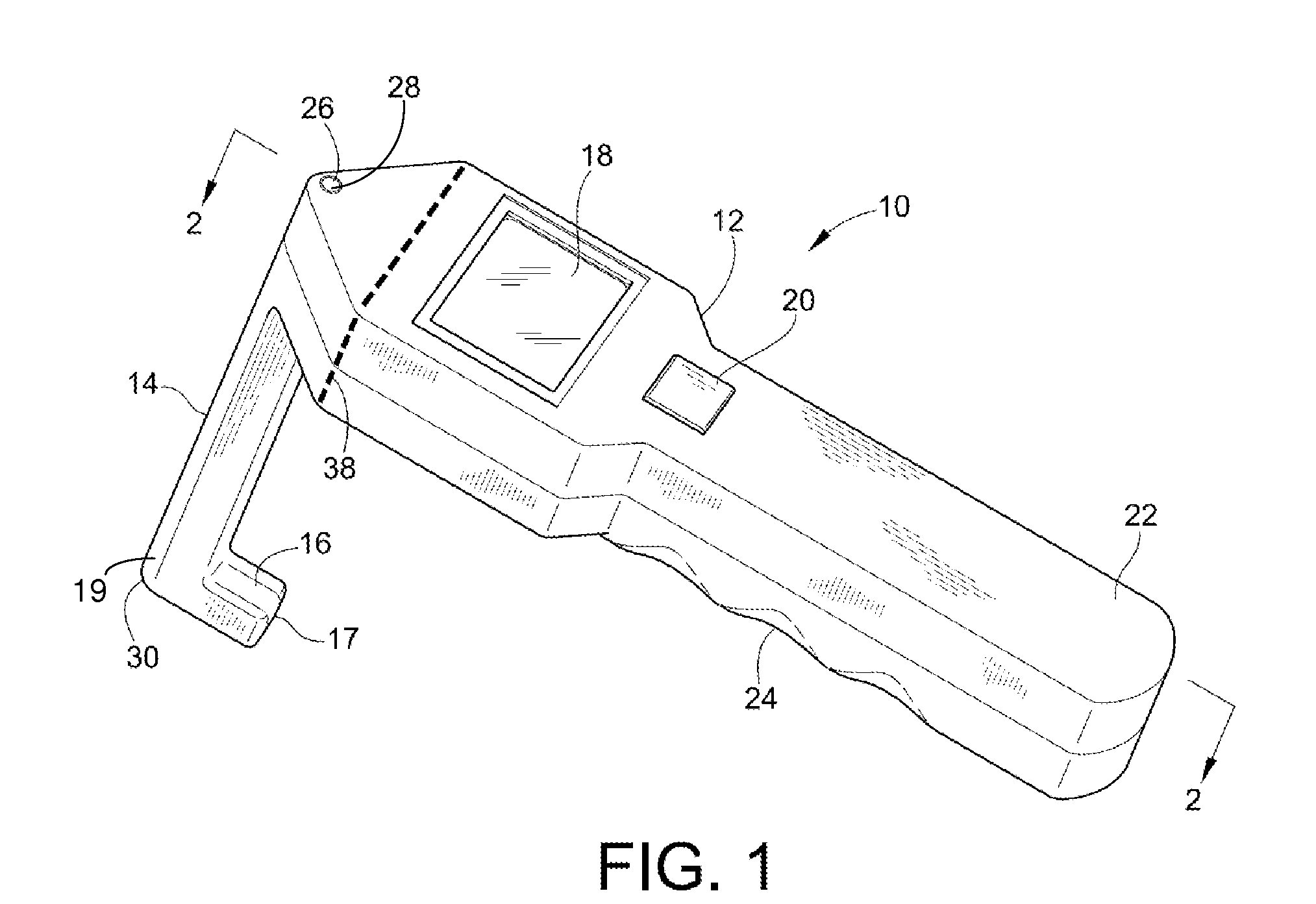
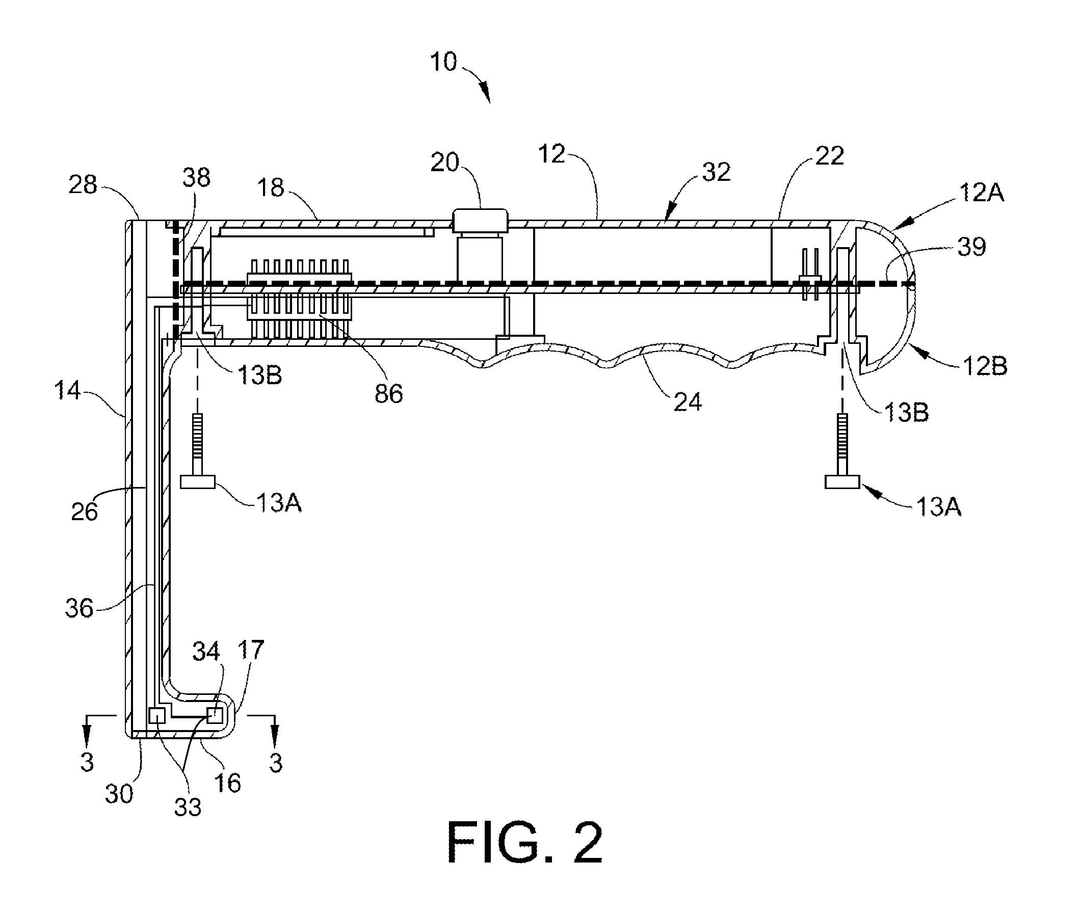
Intramedullary nail targeting device

a nail targeting and intramedullary technology, applied in the field of targeting devices, can solve the problems of increasing flexure, inability to provide the degree of accuracy required for locating and drilling openings, and impractical drilling distal openings in nails, so as to minimize erroneous degrees of freedom and accurate targeting

Inactive Publication Date: 2010-09-30
DURHAM ALFRED A
View PDF100 Cites 73 Cited by
  • Summary
  • Abstract
  • Description
  • Claims
  • Application Information

AI Technical Summary

Benefits of technology

[0018]The present invention advantageously provides magnet members that provide larger magnetic fields in the same space confines, a targeting system that is unaffected by incidental rotation of a magnet member within an intramedullary nail, the ability to use smaller ...

Problems solved by technology

However, these devices fail to provide the degree of accuracy required for locating and drilling openings in intramedullary nails due to the inherent flexure in these devices.
Furthermore, the flexure increases as the length of the arm increases, which renders them impractical for drilling distal openings in the nails.
These device...

Method used


Image

  • Intramedullary nail targeting device
  • Intramedullary nail targeting device
  • Intramedullary nail targeting device

Examples


Embodiment Construction

Definitions

[0036]Unless explicitly stated otherwise, “x axis,”“y axis,” and “z axis” used in reference to the intramedullary nail 60 or the magnet member 70 inserted in the intramedullary nail 60 are defined relative to the intramedullary nail 60 having screw openings 64,66,68 shown in FIGS. 5 and 6. “X axis” refers to an axis defined by the long axis of the intramedullary nail 60. “Y axis” refers to an axis defined by the central axis of screw opening 68, which is substantially orthogonal to the long axis of the intramedullary nail 60 and to screw openings 64,66. “Z axis” refers to an axis defined by the central axis of screw openings 64,66, which are substantially orthogonal to the long axis of the intramedullary nail 60 and to screw opening 68. Thus, in FIGS. 5 and 6, the x axis runs the length of the depicted intramedullary nail 60 from its left-hand side to its right-hand side; the y axis runs perpendicular to the length of the depicted intramedullary nail 60 through screw open...


PUM


Abstract

An intramedullary nail targeting apparatus for targeting and drilling screw openings in the intramedullay nail is provided herein. A preferred version of the targeting apparatus includes a magnetic targeting device, a nail extension for connecting to an intramedullary nail, and a magnet member, preferably in a “bucking configuration,” for affixing to the intramedullary nail at a defined position relative to the screw openings in the nail. The nail extension includes a targeting arm with one or more bores which align with the screw openings in the nail when the targeting arm is aligned with the intramedullary nail. The magnetic targeting device includes a support member with a sensor array that extends through one of the bores on the targeting arm to target the magnet member, thereby aligning the targeting arm with the intramedullary nail. A second bore on the targeting arm can then be used for drilling through the bone at the position of an aligned screw opening. Methods for using the targeting apparatus for targeting and drilling screw openings in intramedullary nails or openings in bone plates are also described herein.

Description

CROSS-REFERENCE TO RELATED APPLICATIONS[0001]This application claims priority under 35 USC §119(e) to U.S. Provisional Patent Application 61 / 214,060 filed Apr. 20, 2009, and is a continuation-in-part under 35 USC §120 of U.S. patent application Ser. No. 12 / 552,726 filed Sep. 2, 2009, which claims priority under 35 USC §119(e) to U.S. Provisional Patent Application 61 / 190,709 filed Sep. 2, 2008 and is a continuation-in-part under 35 USC §120 of U.S. patent application Ser. No. 10 / 679,166 filed Oct. 3, 2003, which claims priority under 35 U.S.C. §119(e) to U.S. Provisional Patent Application 60 / 415,952 filed Oct. 3, 2002, all of which are incorporated herein by reference in their entirety.FIELD OF THE INVENTION[0002]The present invention is directed to a targeting device in general and specifically relates to an intramedullary nail targeting device and method for positioning locking screws for intramedullary nails.BACKGROUND[0003]Devices for targeting of distal holes or openings in or...

Claims


Application Information

Patent Timeline
IPC IPC(8): A61B17/58A61B17/56
CPCA61B5/06A61B5/417A61B5/4504A61B17/808A61B17/1725A61B17/72A61B17/1707A61B5/062
Inventor DURHAM, ALFRED A.
Owner DURHAM ALFRED A
Why Eureka
Try Eureka