Control device

a control device and control technology, applied in the field of control devices, can solve problems such as error correction, error may not be detected, error storage in the memory usually remains uncorrected,

Active Publication Date: 2010-09-30
KK TOSHIBA
View PDF6 Cites 6 Cited by
  • Summary
  • Abstract
  • Description
  • Claims
  • Application Information

AI Technical Summary

Benefits of technology

[0014]An object of the present invention is to provide a control device that can detect the existence of permanent defects of the ECC memory to prevent permanent defects from accumulating and turning into uncorrectable ones without any sign of what is about to happen.

Problems solved by technology

Therefore, an error can be detected but error correction may result in an error because the code word closest to the value is not necessarily the previous code word that has yet to contain an error.
Therefore, the error may not be detected.
However, an error stored in the memory usually remains uncorrected.
That is, if an error stored in the memory is a soft error (temporary error), error correction can be made by storing data again (or overwriting data).
On the other hand, apparently there is a problem that errors caused by permanent defects remain uncorrected and accumulated.
If operation goes on under such circumstances, the number of errors stored in the memory could exceed the correction ability of the ECC and the errors can be uncorrectable without any sign of what is about to happen.
The problem here is that it is impossible to predict the timing when errors turn into uncorrectable errors.
However, if the timing when errors turn into uncorrectable errors is not predictable, the unplanned, immediate suspension of the plant and the like is necessary and the plant and the like can be seriously damaged.
However, if the above error is a soft error, in many cases the error stored in the memory will disappear after the updating of data and the like as described above.
Therefore, it is extremely inefficient for the control device to stop each time the notice is issued.
Moreover, it is difficult to determine whether the issuing of the notice is associated with errors of software or permanent defects.
The reason is that if it is possible to detect the existence of permanent defects, the control device can be stopped at an appropriate timing for maintenance before errors abruptly turn into uncorrectable errors and the plant and the like are seriously damaged.

Method used


Image

  • Control device
  • Control device
  • Control device

Examples


first embodiment

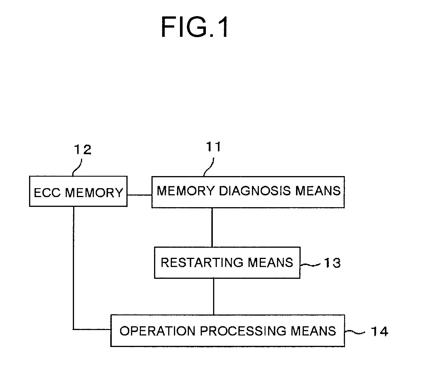
[0037]FIG. 1 is a configuration diagram of a control device according to the present invention. The control device here is for example one that controls a plant such as an electric power generation plant and uses an ECC memory 12 for storing control data. A memory diagnosis means 11 diagnoses the ECC memory 12 of the control device. When the control device is switched on, the memory diagnosis means 11 sets a power-on status and makes a diagnosis of the ECC memory 12. A restarting means 13 restarts the control device based on the result of diagnosis by the memory diagnosis means 11. An operation processing means 14 uses the ECC memory 12 to carry out the control operation of the control device.

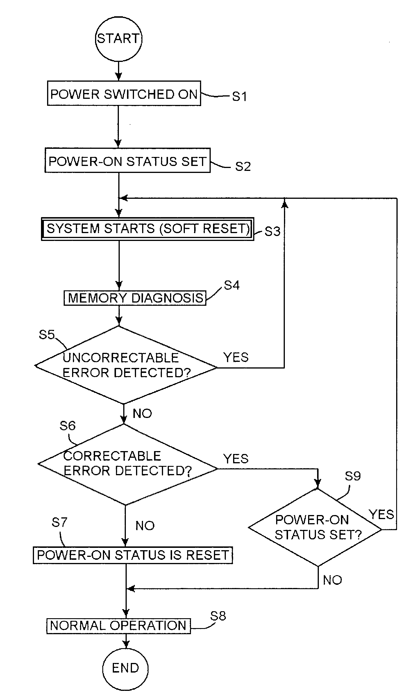
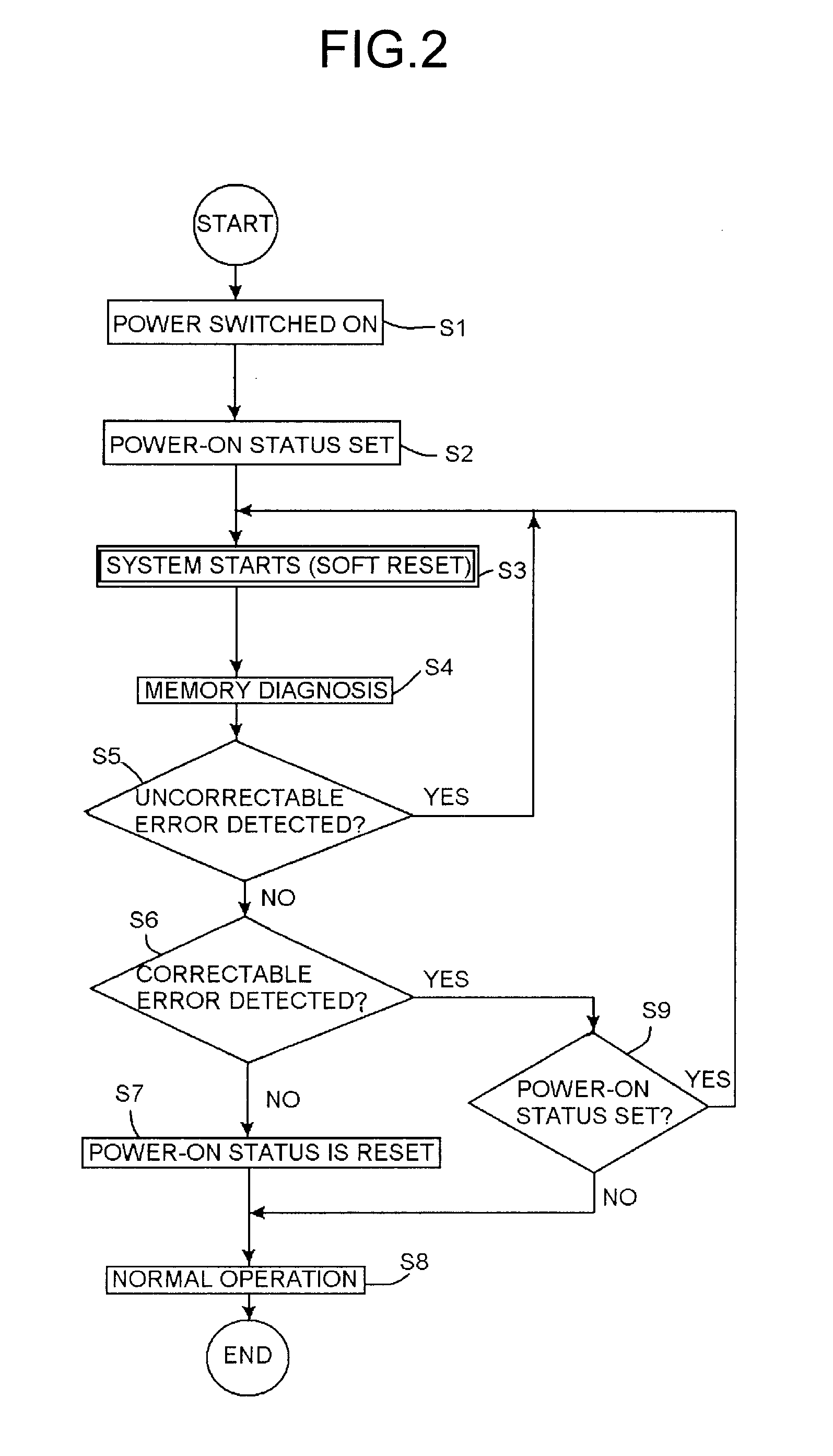
[0038]FIG. 2 is a flowchart illustrating an example of the process of the control device according to the first embodiment of the present invention. When the control device is switched on (S1), the power-on status is set (S2), and a system starts (S3). Subsequently, the memory diagnosis means 1...

second embodiment

[0053]FIG. 5 is a configuration diagram of a control device according to the present invention. An operation processing means 14 uses an ECC memory 12 to perform a control operation. A correctable error detection means 15 detects a correctable error of the ECC memory 12. A permanent defect determination means 16 stores, when error correction is made during a process of reading out data of the ECC memory 12, corrected data to the corresponding address and then reads out the data from the same address again. When error correction is made at the time, the permanent defect determination means 16 issues notice that the corresponding address has a permanent defect.

[0054]FIG. 6 is a flowchart illustrating an example of the process of the permanent defect determination means of the control device according to the second embodiment of the present invention. When a correctable error is detected by the correctable error detection means 15 (S21), the corrected data is stored to the correspondin...

third embodiment

[0063]FIG. 10 is a flowchart illustrating an example of the process of the permanent defect determination means 16 and the system switching means 17 of the control device according to the present invention. When a correctable error is detected by the correctable error detection means 15 (S21), then the corrected data is stored to the corresponding address (S22) and data is read from the corresponding address (S22). At this time, a determination is made as to whether error correction is made, i.e. whether a correctable error is detected (S24). When a correctable error is detected, the notice that the corresponding address has a permanent defect is issued (S25). Then, a determination is made as to whether the element from which the permanent defect is detected is multiplexed and whether the element belongs to the normally used system (S26). When the element from which the permanent defect is detected is multiplexed and belongs to the normally used system, the system switching means 17...


PUM


Abstract

A control device includes: memory diagnosis means for setting a power-on status when an electric power is turned on and diagnosing an ECC memory; restarting means for restarting the control device when the memory diagnosis means detects a correctable error of the ECC memory during the power-on status of the ECC memory; and operation processing means for resetting the power-on status and performing a normal operation when the memory diagnosis means does not detect a correctable error of the ECC memory, while performing the normal operation when a correctable error of the ECC memory is detected because of the restart of the control device by soft reset after the reset of the power-on status but when the control device is not in the power-on status.

Description

CROSS REFERENCES TO RELATED APPLICATIONS[0001]This application is a continuation-in-part (CIP) application based upon the International Application PCT / JP2008 / 003697, the International Filing Date of which is Dec. 10, 2008, the entire content of which is incorporated herein by reference, and claims the benefit of priority from the prior Japanese Patent Application No. 2007-322839, filed in the Japanese Patent Office on Dec. 14, 2007, the entire content of which is incorporated herein by reference.BACKGROUND OF THE INVENTION[0002]The present invention relates to a control device that uses an ECC (Error Check and Correct) memory having a function of automatically correcting errors.[0003]In a control device of an electric power generation plant or the like, an ECC memory is used for a main memory (main storage unit) to store control data that a CPU (central processing unit) reads and writes directly. When data is stored in the memory, the ECC memory adds an error-correcting code, ECC, ...

Claims


Application Information

Patent Timeline
Patent Type & Authority Applications(United States)
IPC IPC(8): G06F11/07
CPCG06F11/1008G06F11/1417G06F11/2284G11C2029/0411G11C29/76G11C2029/0407G11C29/42
Inventor YOSHIDA, YUKITAKASHIGIHARA, KENJINITTA, YOSHIYUKISATO, YUUICHIOMAGARI, TAKASHI
Owner KK TOSHIBA
Why Eureka
Try Eureka