Safety nosing components and manufacturing methods

a technology of safety components and manufacturing methods, applied in the field of safety components, can solve problems such as lack of orientation, physical injury, and risk, and achieve the effect of avoiding accidents, avoiding accidents, and avoiding accidents

Inactive Publication Date: 2010-10-07
KAY RONALD J
View PDF19 Cites 17 Cited by
  • Summary
  • Abstract
  • Description
  • Claims
  • Application Information

AI Technical Summary

Benefits of technology

[0009]The improved safety nosing component and methods of the present invention fulfill the deficiencies in design, manufacturability and functionality of prior art devices. The present invention includes improved material compositions and material requirements. Additionally, the present invention is flexible in design thereby reducing cost and time associated with manufacturing. Embodiments according to the present invention contemplate one-step, two-step, or three-step manufacturing processes. Certain embodiments of the present invention may also provide functionality in addition to a visual safety marker.
[0015]In another embodiment of the present invention, an edge of the main member and a border of the support member are united via a living hinge member. A living hinge member is a thin flexible hinge that may be formed during manufacturing such as by injection molding or may be a separate part such as a thin strip of material, such as thermoset or thermoplastic resin, polyethylene or polypropylene, that is molded into the component to create a line along which the component can bend. Properly designed and executed, the living hinge member can be closed and opened over the life of the component with little or no loss of function.
[0022]In another embodiment of the present invention, the safety nosing component further includes a substrate element. The substrate element includes a top face and a bottom face along with a first side, second side, third side and fourth side. The substrate element according to the present invention is made of any material that can be molded or extruded, for example metal such as aluminum, or polymers. Additionally, the substrate element may include a substance such as a film, pad, metal, grit or tape such as a pre-finished, cut to size, non-skid friction substance and may further include a self adhesive backing used in co-extrusion or triple-extrusion processes. The substrate element is any length, width, depth, shape or size to be positioned adjacent to the light emission element. The advantages of a substrate element are that it may optimize the illumination of the light emission element by preventing the base element from “bleeding through” the light emission element. In a preferred embodiment, the substrate element is white although any color is contemplated to achieve the advantages discussed herein.
[0036]In one embodiment of the present invention, the safety nosing component is overmolded, otherwise referred to as in-molded. Overmolding improves efficiency and can be achieved with injection molding, insert injection molding, or two-shot molding manufacturing processes. With overmolding, only one element of the component is molded in one material, and that element is manipulated so an additional material can be molded around, over, under, or through it to complete the final component.
[0043]Yet another object of the present invention is to reduce risks that may occur when people attempt to navigate in poorly lit environments. The present invention provides components that function as a safety egress or ingress pathway to quickly evacuate people in the case of an emergency.
[0050]Another object of the present invention is to protect architectural structures from wear and maintenance regardless of substance, e.g., such as wood, composite wood, cement, fiberglass, metal, concrete, steel, stone, brick, glass, asphalt, carpet.

Problems solved by technology

Many environments exist where various poor lighting scenarios occur, for example, dimmed lighting or darkness due to a power failure or smoke resultant from a fire.
Risks may occur when people attempt to navigate in poorly lit environments; such risks include physical injury, lack of orientation, lack of information regarding navigation and lack of familiarity with the environment.
But, these prior art devices are deficient in several respects including limitations in design, manufacturability and functionality.
One limitation is due in part to material compositions of the device.
Another limitation of the prior art devices is due in part to material requirements such as an adhesive.
Yet another limitation of the prior art devices is due in part to inflexibility in design, which further results in costly and time-consuming manufacturing.
These prior art devices are limited in functionality by only serving as a safety device.

Method used


Image

  • Safety nosing components and manufacturing methods
  • Safety nosing components and manufacturing methods
  • Safety nosing components and manufacturing methods

Examples


Embodiment Construction

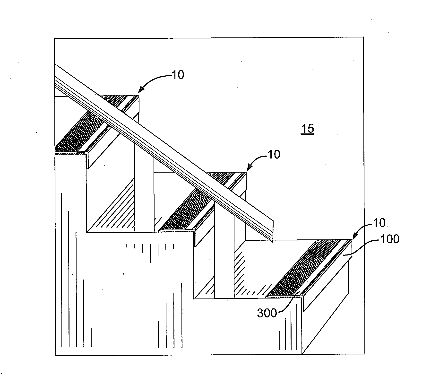
[0063]Preferred embodiments of a protective flooring device according to the present invention are generally shown by referring to the accompanying drawings.

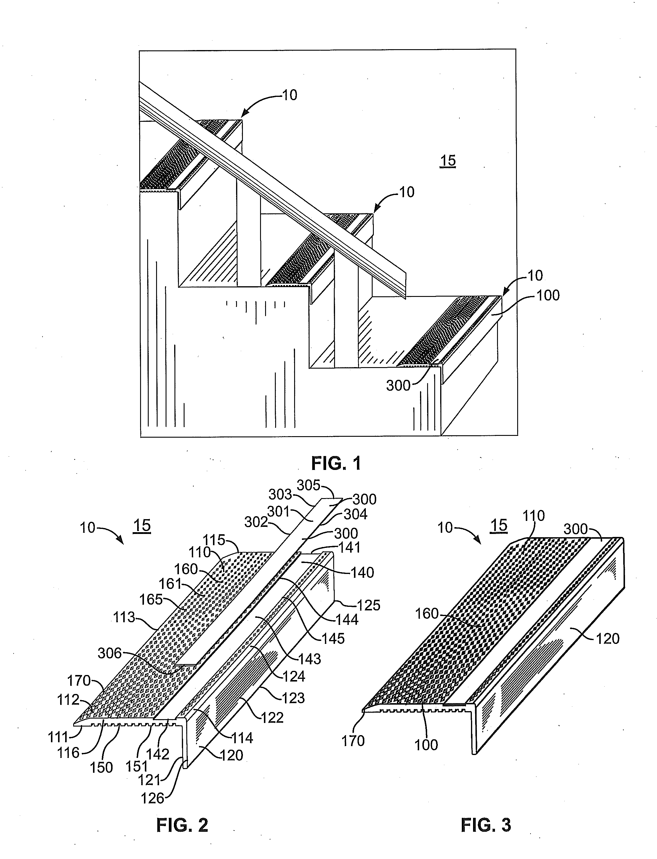
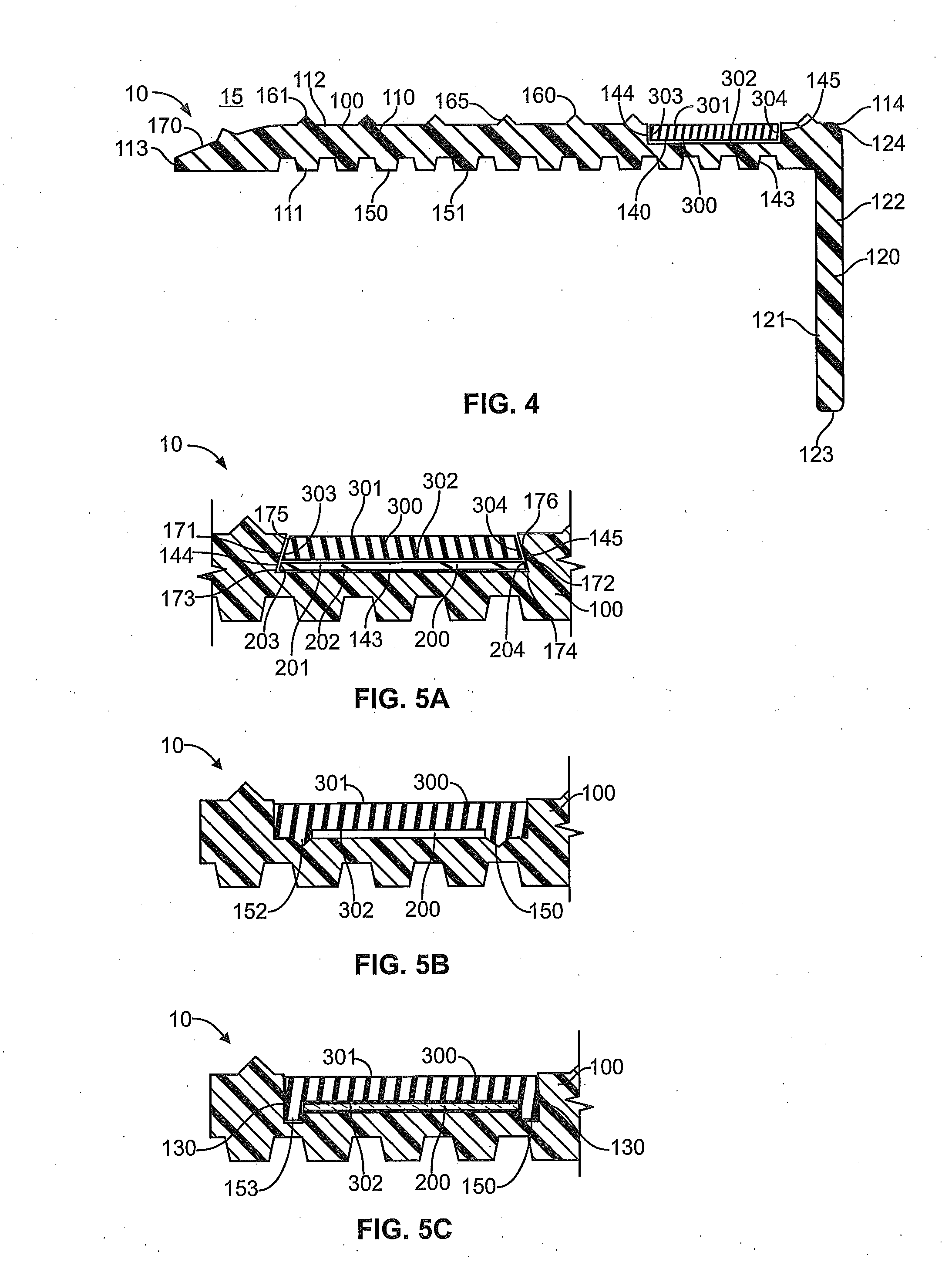
[0064]A safety nosing component 10 is shown in FIG. 1 as stair nosing component 15 in accordance with one embodiment of the present invention. As shown in FIG. 1, FIG. 2, FIG. 3 and FIG. 4, the stair nosing component 15 according to the present invention includes a base element 100 and light emission element 300. Additional embodiments may further include a substrate element 200 as shown in FIG. 5A, FIG. 5B and FIG. 5C.

[0065]In FIG. 1, FIG. 2, FIG. 3 and FIG. 4, the base element 100 includes a main member 110 with an inside surface 111, outside surface 112, first edge 113, second edge 114, third edge 115 and fourth edge 116.

[0066]In this embodiment, the base element 100 includes a main member 110 as described above as well as a support member 120. The support member 120 includes an interior surface 121, exterior surface 122, fir...


PUM


Abstract

The present invention is an improved safety nosing component including a base element with channel member and a light emission element. The safety nosing component is manufactured by extrusion, co-extrusion, triple-extrusion, injection molding, insert injection molding, two-shot molding or a combination thereof. The present invention allows safety nosing components to be installed on architectural structures while also providing additional functionality.

Description

[0001]This application claims the benefit of U.S. Provisional Application No. 61 / 005,739 filed Dec. 7, 2007.FIELD OF THE INVENTION[0002]The present invention relates generally to safety components and more particularly to nosing components for architectural structures and improved manufacturing thereof.BACKGROUND OF THE INVENTION[0003]Safety devices are used on architectural structures in a variety of environments to reduce risk. Many environments exist where various poor lighting scenarios occur, for example, dimmed lighting or darkness due to a power failure or smoke resultant from a fire. Risks may occur when people attempt to navigate in poorly lit environments; such risks include physical injury, lack of orientation, lack of information regarding navigation and lack of familiarity with the environment. To, mitigate these risks, illuminated safety devices exist that are typically installed on stairs, floors, walls, and handrails such as that disclosed in application Ser. No. 12 / ...

Claims


Application Information

Patent Timeline
Patent Type & Authority Applications(United States)
IPC IPC(8): E04F11/16
CPCE04F11/166
Inventor KAY, RONALD J.
Owner KAY RONALD J
Why Eureka
Try Eureka