Ultrasonic inspection device and ultrasonic inspection method

a technology of ultrasonic inspection and ultrasonic inspection, which is applied in the direction of measurement devices, instruments, specific gravity measurements, etc., can solve the problems of difficult to fix an inspection object in a complicated shape with high accuracy and reproducibility, and a lot of time is required to teach and register

Inactive Publication Date: 2010-10-07
KK TOSHIBA
View PDF9 Cites 37 Cited by
  • Summary
  • Abstract
  • Description
  • Claims
  • Application Information

AI Technical Summary

Benefits of technology

[0018]An aspect of the ultrasonic inspection device of the present invention is an ultrasonic inspection device which drives a plurality of piezoelectric transducing parts constituting an ultrasonic transducer, the plural piezoelectric transducing parts being arranged in a matrix or in a line and independently formed, and performs aperture synthesis processing on electric signals generated by the plural piezoelectric transducing parts by receiving, from an inspection object, reflection echoes of ultrasonic waves emitted from the driven piezoelectric transducing parts, to synthesize a three-dimensional image of an inside of the inspection object, the ultrasonic inspection device including: a distance measuring ultrasonic sensor provided in the ultrasonic transducer, for detecting a distance between the ultrasonic transducer and a surface of the inspection object and an inclination of the ultrasonic transducer with respect to the surface of the inspection object, to control the distance and the inclination of the ultrasonic transducer with respect to the inspection object based on information detected by the distance measuring ultrasonic sensor, wherein at least part of ultrasonic wave transmission / reception by the distance measuring ultrasonic sensor is performed during execution of the aperture synthesis processing during which ultrasonic wave transmission / reception by the ultrasonic transducer is not performed.
[0019]Another aspect of the ultrasonic inspection device of the present invention is an ultrasonic inspection device which drives a plurality of piezoelectric transducing parts constituting an ultrasonic transducer, the plural piezoelectric transducing parts being arranged in a matrix or in a line and independently formed, and performs aperture synthesis processing on electric signals generated by the plural piezoelectric transducing parts by receiving, from an inspection object, reflection echoes of ultrasonic waves emitted from the driven piezoelectric transducing parts, to synthesize a three-dimensional image of an inside of the inspection object, the ultrasonic inspection device including: a distance measuring device which calculates a distance between the ultrasonic transducer and a surface of the inspection object and an inclination of the ultrasonic transducer with respect to the surface of the inspection object, from the electric signals by the ultrasonic transducer, to control the distance and the inclination of the ultrasonic transducer with respect to the inspection object based on calculation results by the distance measuring device.
[0020]An aspect of the ultrasonic inspection method of the present invention is an ultrasonic inspection method of driving a plurality of piezoelectric transducing parts constituting an ultrasonic transducer, the plural piezoelectric transducing parts being arranged in a matrix or in a line and independently formed, and performing aperture synthesis processing on electric signals generated by the plural piezoelectric transducing parts by receiving, from an inspection object, reflection echoes of ultrasonic waves emitted from the driven piezoelectric transducing parts, to synthesize a three-dimensional image of an inside of the inspection object, the ultrasonic inspection method including: providing a distance measuring ultrasonic sensor in the ultrasonic transducer, for detecting a distance between the ultrasonic transducer and a surface of the inspection object and an inclination of the ultrasonic transducer with respect to the surface of the inspection object, to control the distance and the inclination of the ultrasonic transducer with respect to the inspection object based on information detected by the distance measuring ultrasonic sensor; and performing at least part of ultrasonic wave transmission / reception by the distance measuring ultrasonic sensor during execution of the aperture synthesis processing during which ultrasonic wave transmission / reception by the ultrasonic transducer is not performed.
[0021]Another aspect of the ultrasonic inspection method of the present invention is an ultrasonic inspection method of driving a plurality of piezoelectric transducing parts constituting an ultrasonic transducer, the plural piezoelectric transducing parts being arranged in a matrix or in a line and independently formed, and performing aperture synthesis processing on electric signals generated by the plural piezoelectric transducing parts by receiving, from an inspection object, reflection echoes of ultrasonic waves emitted from the driven piezoelectric transducing parts, to synthesize a three-dimensional image of an inside of the inspection object, the ultrasonic inspection method including: calculating a distance between the ultrasonic transducer and a surface of the inspection object and an inclination of the ultrasonic transducer with respect to the surface of the inspection object, from the electric signals by the ultrasonic transducer, to control the distance and the inclination of the ultrasonic transducer with respect to the inspection object based on calculation results.

Problems solved by technology

However, the path information is based on the ideal shape design data, and therefore inconsistency may occur between the data and the actual shape of the inspection object, due to the working accuracy.
Further, the inspect ion object is subjected to inspection while being fixed in the scanner mechanism, in which it is not easy to fix an inspection object in a complicated shape with high accuracy and high reproducibility.
Further, in the method of actually driving the scanner mechanism and teaching and registering path information point by point, a lot of time is required to teach and register path information point by point.
Especially for a scanner mechanism having a complicated axis configuration, very complicated procedure and operation are necessary to teach and register path information, and therefore teaching and registering exact path information is a work accompanied by great difficulties.
Further, even after obtaining shape data, there occurs inconsistency in path information unless the inspection object is accurately set in the scanner mechanism.
Further, also in the method of obtaining the actual shape by distance measurement by a distance sensor, unless the inspection object is accurately set in the scanner mechanism after obtaining the shape data, there occurs inconsistency in path information.
As described above, it has been difficult to create the path information which completely coincides with the state of the real inspection object.
However, in the case where the ultrasonic probe is used as the sensor for detecting the distance or the inclination, interference of ultrasonic waves may occur between the detecting ultrasonic transducer and the ultrasonic probe for detecting the distance or the inclination because the ultrasonic probe uses the same ultrasonic wave as that of the ultrasonic transducer used for ultrasonic inspection.
Further, in the case where a plurality of ultrasonic probes are used for detecting the distance or the inclination, interference of ultrasonic waves may occur between the plural ultrasonic probes.

Method used


Image

  • Ultrasonic inspection device and ultrasonic inspection method
  • Ultrasonic inspection device and ultrasonic inspection method
  • Ultrasonic inspection device and ultrasonic inspection method

Examples


first embodiment

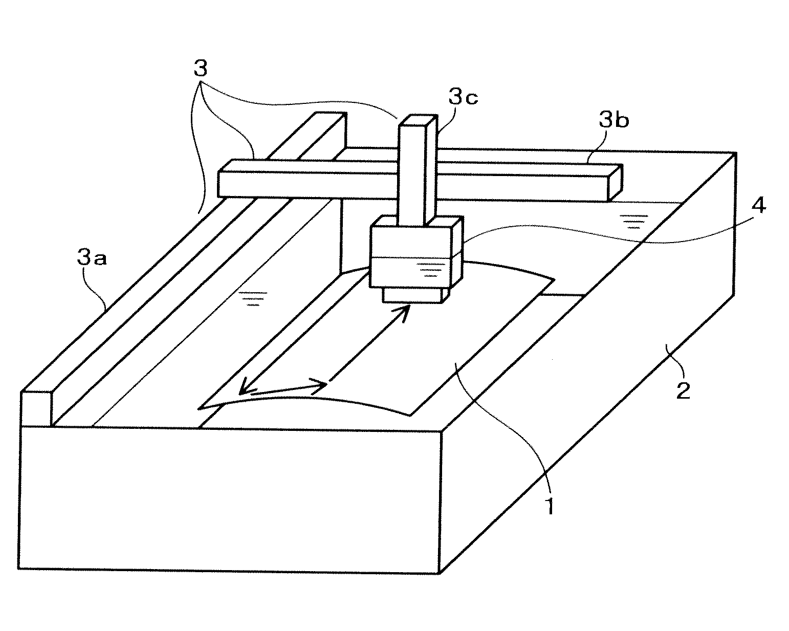
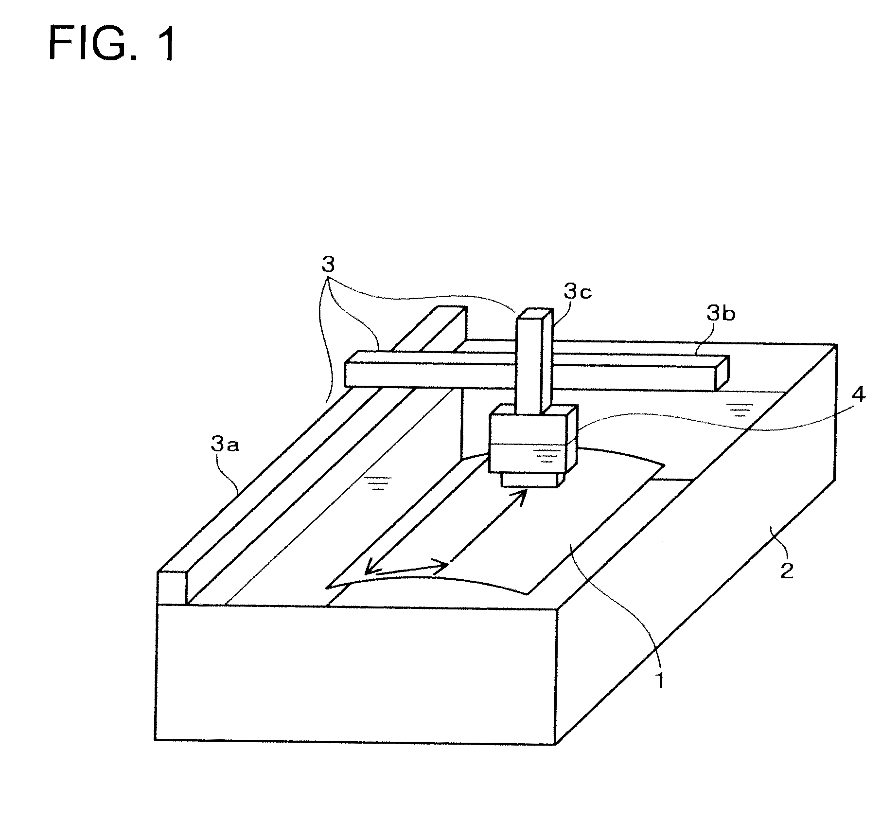
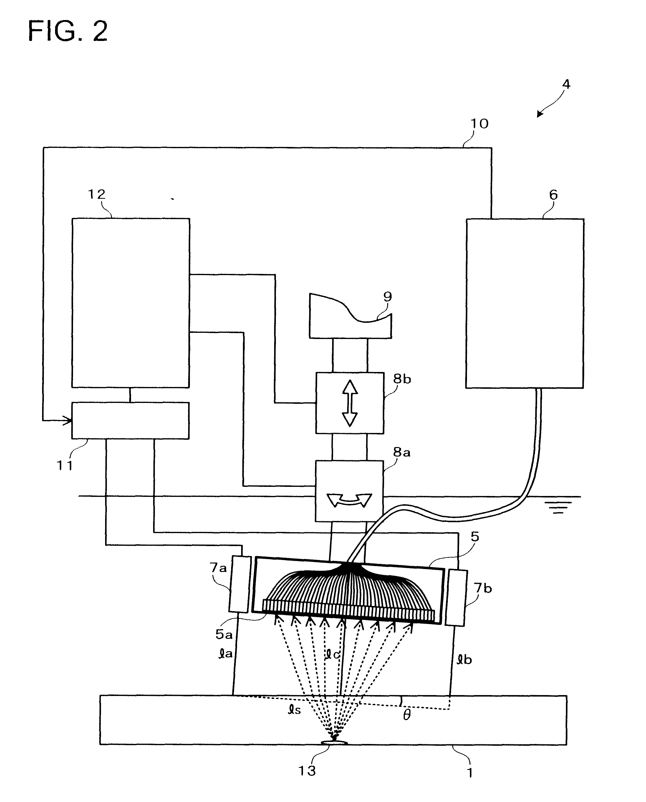
[0033]FIG. 2 is a block diagram schematically showing a configuration of a main part of a first embodiment of the present invention, that is, the outline of the ultrasonic transducer 4 with a position detecting and controlling function shown in FIG. 1. In FIG. 2, numeral 1 denotes the inspection object, and numeral 13 denotes a defect inside the inspection object 1. The ultrasonic inspection device is for inspecting such an inspection object 1 for the defect 13 or the like therein.

[0034]As shown in FIG. 2, the ultrasonic transducer 4 with a position detecting and controlling function includes an ultrasonic transducer 5 composed of a plurality of piezoelectric transducing parts 5a arranged in a matrix or in a line and independently formed. The ultrasonic transducer 5 is electrically connected to a flaw detector 6. The flaw detector 6 drives the ultrasonic transducer 5 to emit ultrasonic waves, receives reflection echoes from the defect inside the inspection object 1 via the ultrasoni...

second embodiment

[0050]FIG. 4 is a diagram showing ultrasonic wave transmission timings of an ultrasonic transducer 5 and distance measuring ultrasonic sensors 7a and 7b according to a second embodiment of the present invention. In FIG. 4, the horizontal axis is a common time axis, and waveforms shown at the upper section, the middle section, and the lower section are synchronized along the time axis.

[0051]In this second embodiment, the frequency band of the ultrasonic wave used by the distance measuring ultrasonic sensor 7a is different from that in the first embodiment. The other device configuration is the same as that of the first embodiment. The second embodiment is made to cope with the case in which the time of the aperture synthesis processing in one unit processing which is mainly composed of the ultrasonic wave transmission by the ultrasonic transducer 5 and the aperture synthesis processing is short.

[0052]In such a case, two distance measurement ultrasonic signals 15a and 15b cannot be tr...

third embodiment

[0060]FIG. 6 is a diagram schematically showing a main part of an ultrasonic inspection device according to a third embodiment of the present invention, that is, the outline of the ultrasonic transducer 4 with a position detecting and controlling function shown in FIG. 1. In FIG. 6, numeral 1 denotes an inspection object, and numeral 13 denotes a defect inside the inspection object 1. The ultrasonic inspection device is for inspecting such an inspection object 1 for the defect 13 or the like therein.

[0061]As shown in FIG. 6, the ultrasonic transducer 4 with a position detecting and controlling function includes an ultrasonic transducer 5 composed of a plurality of piezoelectric transducing parts 5a arranged in a matrix or in a line and independently formed. The ultrasonic transducer 5 is electrically connected to a flaw detector 6. The flaw detector 6 drives the ultrasonic transducer 5 to emit ultrasonic waves, receives reflection echoes from the defect or the like inside the inspec...


PUM

PropertyMeasurementUnit
piezoelectricaaaaaaaaaa
distance measuringaaaaaaaaaa
distance measuring ultrasonic sensoraaaaaaaaaa

Abstract

An ultrasonic transducer is provided with a distance measuring ultrasonic sensor for detecting a distance between the ultrasonic transducer and a surface of an inspection object and an inclination of the ultrasonic transducer with respect to the surface of the inspection object, to control the distance and the inclination of the ultrasonic transducer with respect to the inspection object based on information detected by the distance measuring ultrasonic sensor, and at least part of ultrasonic wave transmission/reception by the distance measuring ultrasonic sensor is performed during execution of aperture synthesis processing during which transmission/reception by the ultrasonic transducer is not performed.

Description

CROSS-REFERENCE TO THE INVENTION[0001]This application is based upon and claims the benefit of priority from the prior Japanese Patent Application No. 2009-089757, filed on Apr. 2, 2009; the entire contents of which are incorporated herein by reference.BACKGROUND OF THE INVENTION[0002]1. Field of the Invention[0003]The present invention relates to an ultrasonic inspection device and an ultrasonic inspection method visualizing a state of defect, void, and peeling of a joint portion and the like in a structure and a component, using ultrasonic waves transmitted / received by an ultrasonic transducer composed of a plurality of piezoelectric transducing parts which are arranged in a matrix or in a line and independently formed.[0004]2. Description of the Related Art[0005]In a conventional ultrasonic inspection device using an ultrasonic transducer composed of a plurality of piezoelectric transducing parts which are arranged in a matrix or in a line and independently formed, when the ultra...

Claims


Application Information

Patent Timeline
Patent Type & Authority Applications(United States)
IPC IPC(8): G01N29/04
CPCG01N29/069G01N2291/106G01N2291/0289G01N29/2437
Inventor ISOBE, HIDEOARAI, RYOICHIIKEDA, TAKAHIROYAMANE, NORIYUKI
Owner KK TOSHIBA
Why Eureka
Try Eureka