Load Cell for Sensing Supporting Forces in a Support Element

a technology of supporting force and load cell, which is applied in the direction of measuring devices, instruments, weighing apparatuses, etc., can solve the problem of false detection of the measured resistance values (i.e. forces) in the load cell

Active Publication Date: 2010-10-07
WLKA ALEXANDER WIEGAND SE & CO KG
View PDF10 Cites 8 Cited by
  • Summary
  • Abstract
  • Description
  • Claims
  • Application Information

AI Technical Summary

Benefits of technology

[0010]Embodiments of the present invention advantageously provide a robust load cell for a support element which supplies a signal corresponding to the load borne by the support element, i.e. the supporting force, which can be easily mounted to the end of the support leg, which it is little influenced by transverse forces and moments, and which is capable of withstanding environmental influences such as moisture and dirt.

Problems solved by technology

Thus, considerable differences in temperature can result which may falsify the measured resistance values (i.e. forces) in the load cell.

Method used


Image

  • Load Cell for Sensing Supporting Forces in a Support Element
  • Load Cell for Sensing Supporting Forces in a Support Element
  • Load Cell for Sensing Supporting Forces in a Support Element

Examples


Embodiment Construction

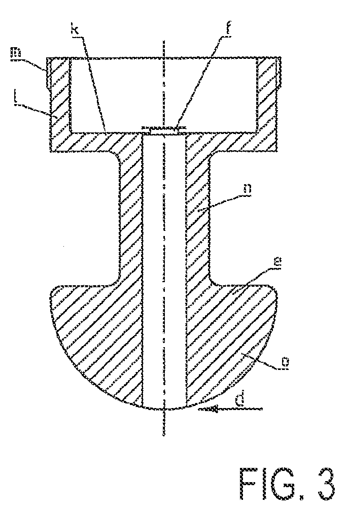
[0028]In accordance with FIG. 3, an embodiment of the load cell includes a rust-proof deformation member e made of steel the strain of which caused by the force to be measured is not detected by strain gauges glued onto the member but with the aid of strain-sensitive resistors manufactured by thin-film technology. This has the advantage of high long-term stability, as the thin-film resistors manufactured by thin-film technology are not glued on but are adhesively sputtered onto a carrier member as atomic compound.

[0029]According to FIG. 4a, 4b, the thin-film resistors are provided on the end face of the flat cylindrical carrier member f initially separated from the load cell whose material corresponds to the material of the deforming member or at least exhibits a similar heat expansion. During the manufacturing process of the load cell the carrier member is adhesively joined to the deformation member at its outer edge g with the aid of a welding laser or by electron beam welding.

[00...


PUM

PropertyMeasurementUnit
supporting forceaaaaaaaaaa
transverse forcesaaaaaaaaaa
resistancesaaaaaaaaaa

Abstract

A load cell for detecting the supporting force transmitted by a load-bearing support element is provided. The load cell forms a measuring portion of the support element, which deforms under the supporting force and transverse forces in a direction deviating from the supporting force to form part of the support element with the same. A plurality of thin-film resistors are arranged at the measuring portion, and exhibit a reaction proportional to strain and whose reactions proportional to transverse forces cancel each other.

Description

CROSS-REFERENCE TO RELATED APPLICATIONS[0001]This application claims priority to foreign Patent Application DE 10 2009 002 188.4, filed on Apr. 3, 2009, the disclosure of which is incorporated herein by reference in its entirety.FIELD OF THE INVENTION[0002]The invention relates to a load cell for detecting supporting forces in a support element, especially for use in crane vehicles, mobile hoisting gear, mobile drilling units, self-propelled gun carriages or the like.BACKGROUND OF THE INVENTION[0003]In FIG. 1 a crane vehicle is schematically illustrated which is put on support legs a serving as support element to safeguard the stand during operation. The support elements a are usually provided at the end of telescopic carriers b secured to the base frame c of the vehicle. At the site of the crane the entire vehicle is hydraulically lifted with the aid of the support elements. The vehicle wheels are not in contact with the ground.[0004]When the forces transmitted vertically into the ...

Claims


Application Information

Patent Timeline
Patent Type & Authority Applications(United States)
IPC IPC(8): G01L1/22
CPCG01G3/14G01L1/2231G01G19/12
Inventor HOSE VON WOLFFRAMSDORFF, JOACHIMJOST, OLIVERHAERLE, KLAUSAMENDT, STEFAN
Owner WLKA ALEXANDER WIEGAND SE & CO KG
Why Eureka
Try Eureka