Method of returning pointer to origin point

a pointer and origin point technology, applied in the direction of dynamo-electric converter control, program control, instruments, etc., can solve the problems of inability to detect the stopper, the difficulty of stopping the pointer at the zero indicating position,

Active Publication Date: 2010-10-07
YAZAKI CORP
View PDF16 Cites 9 Cited by
  • Summary
  • Abstract
  • Description
  • Claims
  • Application Information

AI Technical Summary

Benefits of technology

[0017]According to the method of returning the pointer to the origin point as mentioned above, when the point of time when a time necessary for the pointer to move from the detection point to the origin point (movement time) has elapsed from the timing of the detection of the actual pointer by the sensor at the detection point while the actual pointer is moving is the predetermined point of time, both the position of the pointer in the control and the actual position of the pointer return to the origin point at the predetermined point of time. Consequently, the pointer can be accurately returned to the origin point both for the position in the control and for the actual position.

Problems solved by technology

However, since the control of the stepper motor is an open loop control, there are cases where the rotation amount (or rotation position) in the control and the actual rotation amount (or rotation position) are different from each other because of a loss of synchronization.
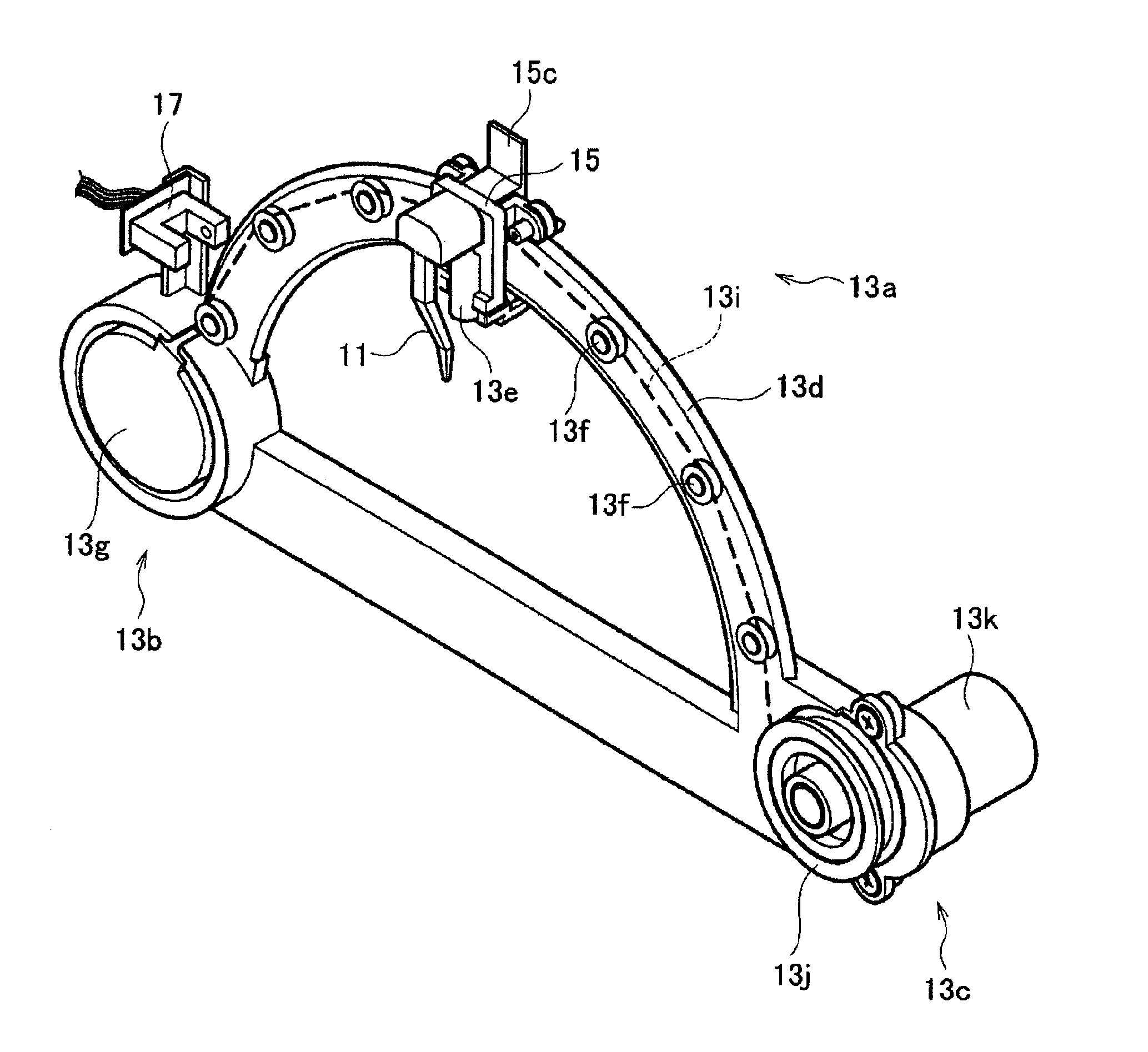
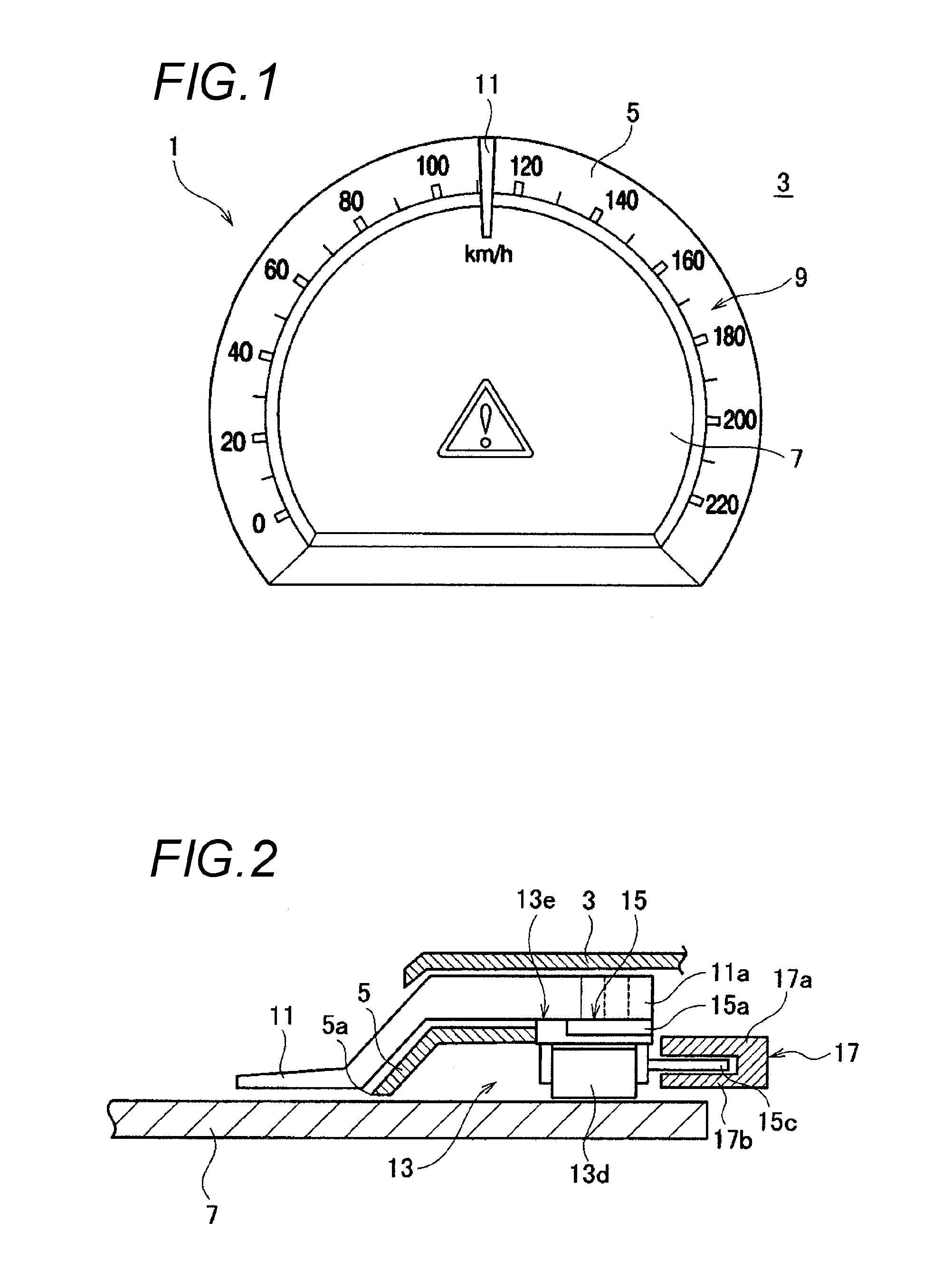
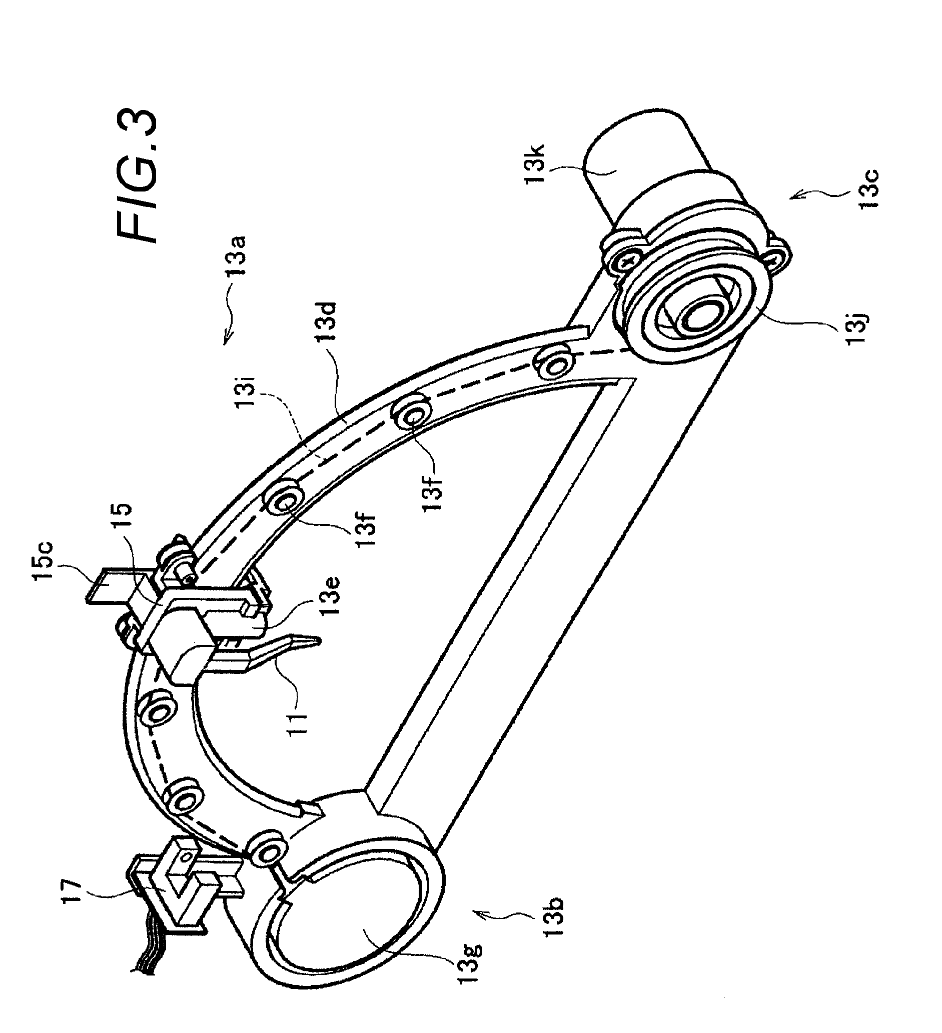
In this moving mechanism, since only the linear member has the same movement amount as that of the pointer, it is difficult to stop the pointer at the zero indicating position by using the stopper and the stopper piece like those of the conventional measuring instruments in which the pointer is rotated.
However, in the above-described moving mechanism, since the pushing force in the winding direction is not applied to the linear member when the pointer stops at the zero indicating position, a change of the current flowing through the coil of the stepper motor does not occur, so that the stopping of the pointer cannot be detected.

Method used


Image

  • Method of returning pointer to origin point
  • Method of returning pointer to origin point
  • Method of returning pointer to origin point

Examples


modification 1

[0055](Modification 1)

[0056]In the present embodiment, in performing the return-to-origin-point processing for an abnormal case, whether the actual pointer 11 has reached the zero indicating position or not is checked while the position of the pointer 11 in the control is being moved toward the starting point from the reference point, beyond the zero indicating position, normally rotated ten degrees from the starting point of the movement range. However, in the return-to-origin-point processing for an abnormal case, whether the actual pointer 11 has reached the zero indicating position or not may be checked while the position of the pointer 11 in the control is being normally rotated ten degrees from the starting point of the movement range to the reference point beyond the zero indicating position.

[0057]A pointer-type measuring instrument 1 according to a modification of the present invention has such a structure. The microcomputer 21 of the pointer-type measuring instrument 1 acco...

modification 2

[0062](Modification 2)

[0063]Further, in the return-to-origin-point processing for an abnormal case, the processing performed at steps S107A, S111 and S113A of the flowchart of FIG. 7 may be executed while the pointer 11 in the control is normally rotated ten degrees from the starting point of the movement area at step S107 of the flowchart of FIG. 6.

[0064]A pointer-type measuring instrument 1 according to a second modification of the present invention has such a structure. The microcomputer 21 of the pointer-type measuring instrument 1 according to the second modification performs the processing shown in the flowchart of FIG. 8 according to a control program stored in the ROM. Of this, the processing of steps S101 to S105 are the same as those of steps S101 to S105 shown in the flowcharts of FIGS. 6 and 7.

[0065]When the reverse rotation angle of the pointer 11 is not less than the maximum deflection angle at step S105 (YES at step S105), the microcomputer 21 of the present modificat...


PUM


Abstract

There is provided a method of returning a pointer driven by a motor to an origin point disposed between a starting point and an endpoint of a movement range of the pointer, the method comprising the steps of: moving the pointer from an arbitrary point in the movement range to a reference point that is away from the starting point by not less than a distance between the starting point and the origin point; thereafter moving the pointer from the reference point toward the starting point; detecting the pointer by a sensor at a detection point whose relative position with respect to the origin point is known; and stopping, when the pointer at the detection point is detected, the pointer moving from the reference point toward the starting point at a predetermined point of time based on timing of the detection of the pointer at the detection point.

Description

BACKGROUND OF THE INVENTION[0001]1. Technical Field[0002]The present invention relates to a technology of moving a pointer by a driving force of a motor to cause the pointer to stop at a predetermined indicating position so as to coincide with an indicating position of the pointer in the control.[0003]2. Background Art[0004]For example, as the driving force of the pointer of a measuring instrument of a vehicle, a stepper motor has been being increasingly used. The stepper motor is advantageous in that the rotation amount of the pointer and the indicating position after rotation can be easily defined by the number of inputted driving pulses. However, since the control of the stepper motor is an open loop control, there are cases where the rotation amount (or rotation position) in the control and the actual rotation amount (or rotation position) are different from each other because of a loss of synchronization.[0005]Therefore, when the pointer is driven by the stepper motor, it is ne...

Claims


Application Information

Patent Timeline
Patent Type & Authority Applications(United States)
IPC IPC(8): G01D11/00G01D11/16
CPCG01D13/22G01D11/16
Inventor YAMADA, YOSHIHISA
Owner YAZAKI CORP
Why Eureka
Try Eureka