Hot water feeder

a feeder and hot water technology, applied in the field can solve the problems of relatively expensive flowmeters, and achieve the effect of reducing the cost of hot water feeders

Inactive Publication Date: 2010-10-07
HONDA MOTOR CO LTD
View PDF5 Cites 15 Cited by
  • Summary
  • Abstract
  • Description
  • Claims
  • Application Information

AI Technical Summary

Benefits of technology

[0005]It is therefore an object of the present invention to provide a technique capable of reducing the cost of a hot water feeder and present the user with information about the cumulative thermal energy generated by the hot water feeder.
[0009]The cumulative thermal energy provided by the hot water feeder can thus be determined because the level of heat exchange can be obtained quickly and appropriately. In addition, there is no need to newly provide a separate flowmeter. The cost of the hot water feeder can therefore be reduced.

Problems solved by technology

A flowmeter is one such part that is relatively expensive.

Method used


Image

  • Hot water feeder
  • Hot water feeder
  • Hot water feeder

Examples


Embodiment Construction

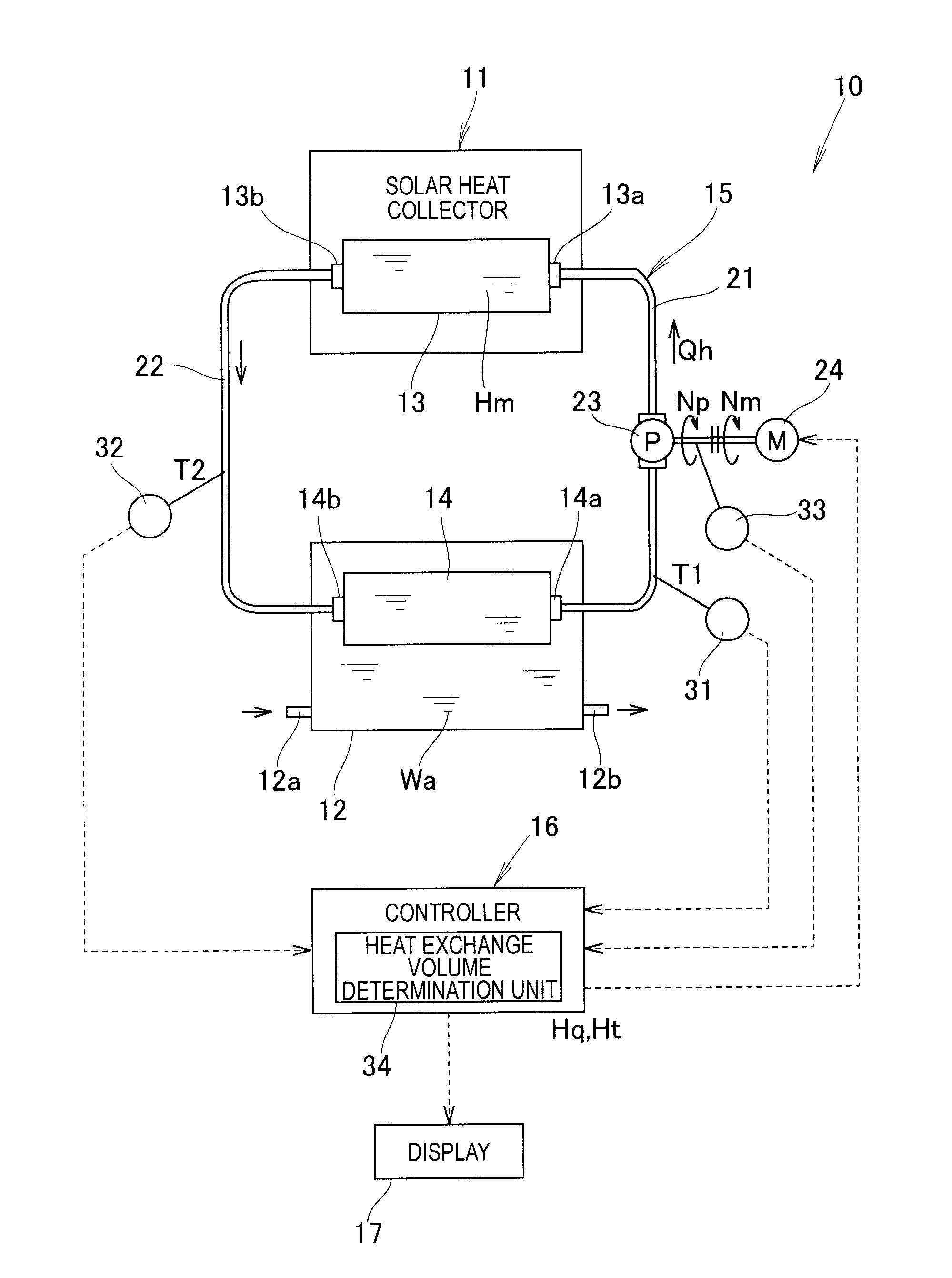
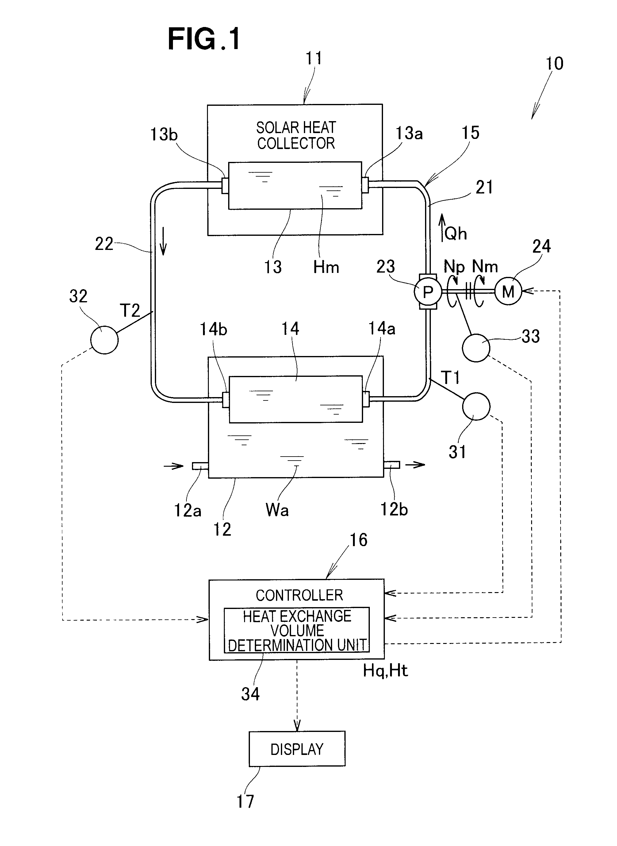
[0016]As shown in FIG. 1, a heat medium material Hm (referred to simply hereinbelow as a “heat medium Hm”) heated by solar heat recovered in the solar heat collector 11 of a hot water feeder 10 is heated, and heat is applied to water Wa in a water or hot-water tank 12 by forcibly circulating the heat medium Hm. An antifreeze, water, or oil, for example, can be used as the heat medium Hm, but these are not the only options, and any fluid (liquid, gas) used to transfer heat may be used.

[0017]Specifically, the hot water feeder 10 has a solar heat collector 11, a hot-water tank 12, a first heat exchanger 13, a second heat exchanger 14, a heat medium circulation system 15, a controller 16, and a display 17.

[0018]The solar heat collector 11 converts solar energy into thermal energy and has a known structure. The first heat exchanger 13 exchanges heat so that the heat medium Hm is heated by the solar heat (thermal energy converted from solar energy) collected by the solar heat collector 11...


PUM


Abstract

A hot water feeder in which a solar heat collector is used. The feeder has a first heat exchanger for heating a heat medium by solar heat, a second heat exchanger for heating water in a hot-water tank by the heated heat medium, and a heat exchange volume determination unit. The heat exchange volume determination unit calculates the flow rate of the heat medium circulating between the first and second heat exchangers on the basis of the detected temperature of the heat medium fed to the first heat exchanger and the rotational speed of a heat medium circulation pump, and calculates the heat exchange volume on basis of the flow rate and the temperature difference between the detected temperatures.

Description

FIELD OF THE INVENTION[0001]The present invention relates to a hot water feeder using a solar heat collector.BACKGROUND OF THE INVENTION[0002]Development of techniques for the effective use of solar heat has continued in recent years. Some of these techniques involve using a hot water feeder to heat water in a hot-water tank by solar heat recovered by a solar heat collector. The technique described in Japanese Utility Model Registration No. 3140747 is known as an example of such a hot water feeder.[0003]The conventional hot water feeder is designed so that hot water heated by a solar heat collector is circulated by a pump and stored in a hot-water tank, and is provided with an incoming water pipe for feeding water to the hot-water tank from the outside, and a outgoing hot water pipe for delivering water from the hot-water tank to the outside. A feed water temperature sensor is mounted in the incoming water pipe, and an outgoing hot water temperature sensor and a flowmeter are mounte...

Claims


Application Information

Patent Timeline
Patent Type & Authority Applications(United States)
IPC IPC(8): F24J2/30G05D23/00G05D9/00F24S10/30F24S90/00
CPCF24D11/003Y02B10/70Y02B10/20F24D19/1042Y02A30/60F24H15/34F24H15/219F24H15/395F24H15/20F24H15/215F24H15/174
Inventor KANAI, YASUSHI
Owner HONDA MOTOR CO LTD
Why Eureka
Try Eureka