Vehicle steering system

a steering system and vehicle technology, applied in the direction of steering initiation, vessel parts, instruments, etc., can solve the problem that the vehicle may acquire a temporal oversteering tendency, and achieve the effect of improving the handling of the vehicl

Inactive Publication Date: 2010-10-07
HONDA MOTOR CO LTD
View PDF12 Cites 5 Cited by
  • Summary
  • Abstract
  • Description
  • Claims
  • Application Information

AI Technical Summary

Benefits of technology

[0005]In view of such problems of the prior art, a primary object of the present invention is to provide a vehicle steering control system for a vehicle equipped with an electric motor operable as a regenerative brake which can avoid changes in the behavior of the vehicle when the regenerative brake is activated, and thereby improve the handling of the vehicle.
[0007]When the rear wheels are braked by a regenerative braking action without substantially applying a brake to the front wheel, the vehicle may acquire a temporal oversteer tendency. However, by increasing the effort required to steer the front wheels, such a tendency can be canceled or compensated, and the vehicle operator is enabled to control the vehicle without experiencing any unfamiliar feeling or discomfort. The effort required to steer the front wheels can be increased by decreasing the assist steering torque or providing a reactive steering torque at such a time.
[0008]According to a preferred embodiment of the present invention, the steering torque control unit reduces a steering assist torque according to a regenerative power of the rear drive electric motor. Preferably, the rear wheels are driven by individual rear drive electric motors, and the steering torque control unit reduces a steering assist torque according to a difference between the regenerative powers of the rear wheels. Thereby, a particularly favorable control of the vehicle behavior can be achieved.

Problems solved by technology

When the rear wheels are braked by a regenerative braking action without substantially applying a brake to the front wheel, the vehicle may acquire a temporal oversteer tendency.

Method used


Image

  • Vehicle steering system
  • Vehicle steering system
  • Vehicle steering system

Examples


Embodiment Construction

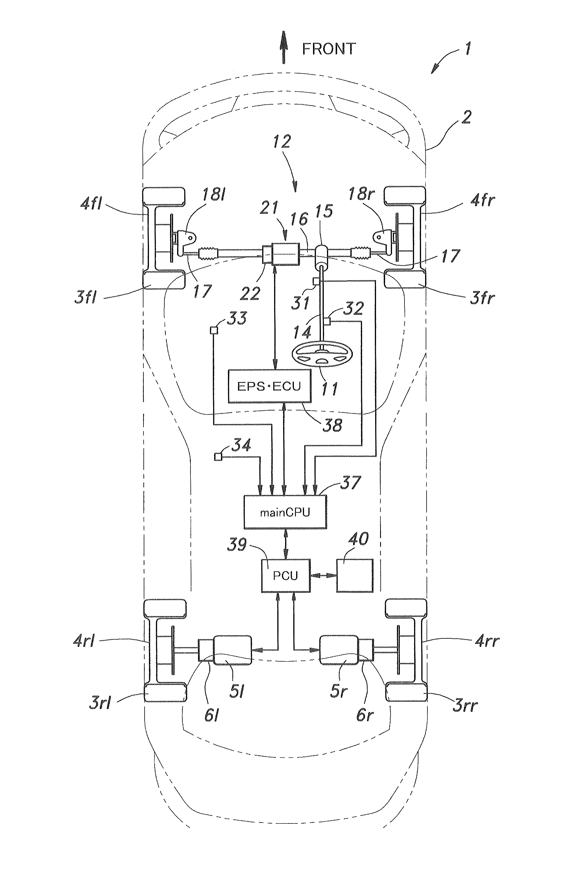
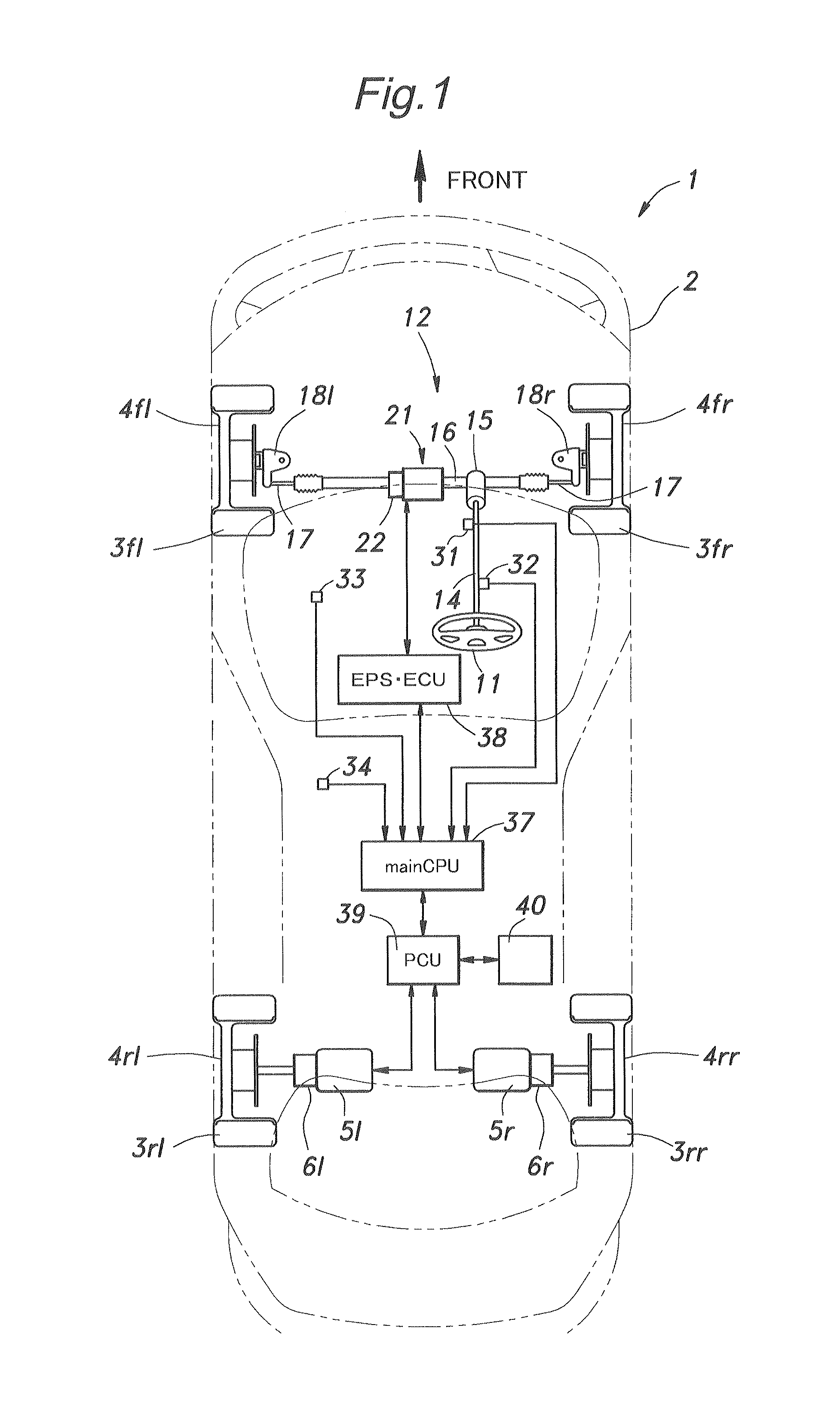
[0020]In the following description, each wheel is denoted with numeral 4 and a suffix indicating the position of the wheel such as 4fl, 4fr, 4rl and 4rr appended thereto. When the wheels are generally referred to, only the numeral 4 may be used to denote each wheel.

[0021]Referring to FIG. 1, a vehicle 1 having a vehicle body 2 is provided with a pair of front wheels 4fl and 4fr each fitted with a pneumatic tire 3fl, 3fr and a pair of rear wheels 4rl and 4rr each fitted with a pneumatic tire 4rl, 4rr, and these wheels are supported by a vehicle body 2 via a corresponding wheel suspension system. The vehicle 1 consists of a four-wheel drive vehicle in which the front wheels are driven by an internal combustion engine not shown in the drawings and the rear wheels are driven by corresponding rear drive motors (rear wheel drive electric motors) 5l and 5r via corresponding gear mechanisms 6l and 6r, respectively.

[0022]The vehicle 1 is provided with a front wheel steering system 12 which a...


PUM


Abstract

In a steering system for a vehicle incorporated with a rear drive electric motor (5) for driving a pair of rear wheels (3rl, 3rr) that can function as a regenerative brake for the rear wheels, a steering torque control unit (38) reduces a steering assist torque provided by the power steering assist unit (21) when the rear drive electric motor is providing a regenerative braking. When the rear wheels are braked by a regenerative braking action without substantially applying a brake to the front wheel, the vehicle may acquire a temporal oversteer tendency. However, by increasing the effort required to steer the front wheels, such a tendency can be canceled or compensated, and the vehicle operator is enabled to control the vehicle without experiencing any unfamiliar feeling or discomfort. The effort required to steer the front wheels can be increased by decreasing the assist steering torque or providing a reactive steering torque at such a time.

Description

TECHNICAL FIELD[0001]The present invention relates to a vehicle steering system that provides an assisting / reactive steering torque, and in particular to a vehicle steering system that adjusts the assisting steering torque according to the condition of the vehicle.BACKGROUND OF THE INVENTION[0002]A vehicle steering system is required to provide a steering reaction that reflects the vehicle condition and road condition for the vehicle operator to operate the vehicle in a comfortable way. The electric power steering system is increasingly widely used in current automobiles, and is often equipped with a control system that provides a reactive torque to the steering wheel according to various parameters such as the steering angle, yaw rate, vehicle speed and so on at the same time as providing an assisting steering torque.[0003]According to a known vehicle steering system, when a disturbance such as a side wind is applied to a vehicle, an assisting steering torque that counteracts the d...

Claims


Application Information

Patent Timeline
Patent Type & Authority Applications(United States)
IPC IPC(8): B62D5/04B60K7/00B62D6/00B62D101/00B62D109/00B62D117/00B62D119/00B62D137/00
CPCB60K1/02B62D11/24B62D5/0463B60K7/0007
Inventor YAMAZAKI, NORIO
Owner HONDA MOTOR CO LTD
Why Eureka
Try Eureka