Method for operating an ignition device

a technology of ignition device and operating method, which is applied in the direction of machines/engines, manufacturing tools, instruments, etc., can solve the problems of inability to operate reliably and impaired optical characteristics of combustion chamber windows, and achieve the effect of reliable operation

Inactive Publication Date: 2010-10-07
ROBERT BOSCH GMBH
View PDF2 Cites 20 Cited by
  • Summary
  • Abstract
  • Description
  • Claims
  • Application Information

AI Technical Summary

Benefits of technology

[0007]Accordingly, the object of the present invention is to improve an operating method for an ignition device, and an ignition device of the aforementioned type, in such a way that reliable operation is provided over a fairly long period of use, in particular when soiling of the combustion chamber window also occurs.

Problems solved by technology

It is disadvantageous that over a period of use of the ignition device the optical characteristics of the combustion chamber window may be impaired, for example because of deposits which collect in particular on a surface of the combustion chamber window on the combustion chamber side.
In particular, transmission of optical radiation to be introduced through the combustion chamber window into the combustion chamber and / or radiation originating from the combustion chamber, for example radiation to be analyzed, may be impaired by the above-described soiling effects, so that reliable operation of the ignition device is no longer possible.

Method used


Image

  • Method for operating an ignition device
  • Method for operating an ignition device
  • Method for operating an ignition device

Examples


Embodiment Construction

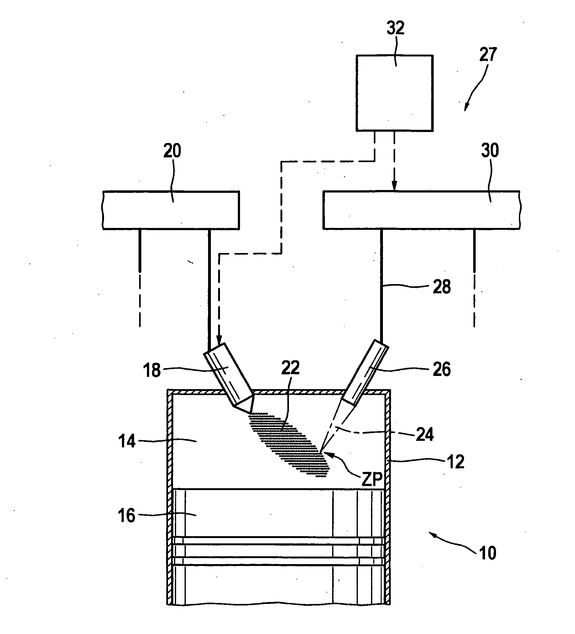
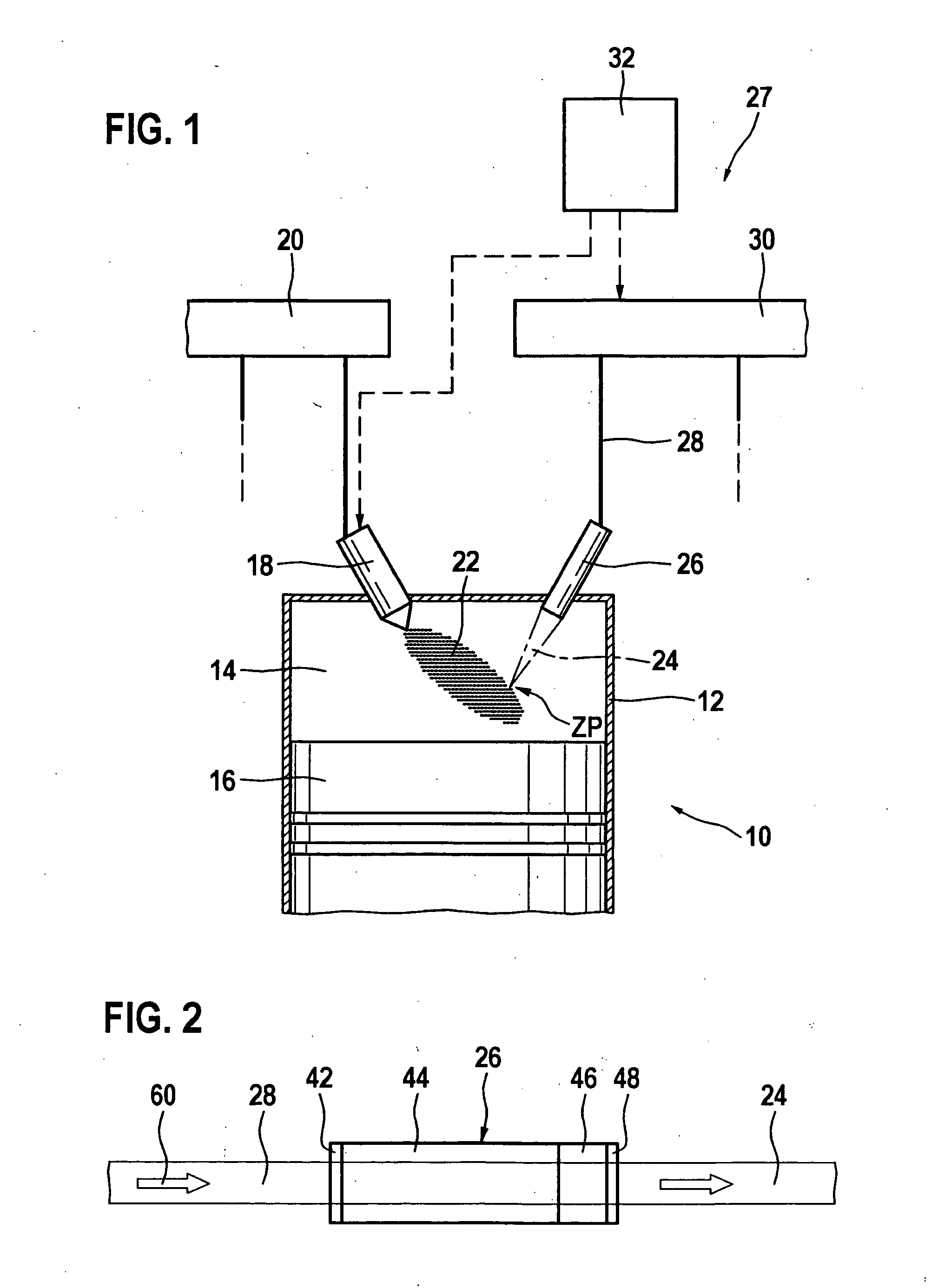
[0036]An internal combustion engine overall is denoted by reference numeral 10 in FIG. 1. The internal combustion engine is used to drive a motor vehicle, not illustrated. Internal combustion engine 10 includes multiple cylinders, of which only one is denoted by reference numeral 12 in FIG. 1. A combustion chamber 14 for cylinder 12 is delimited by a piston 16. Fuel passes directly into combustion chamber 14 via an injector 18 which is connected to a fuel pressure accumulator 20, also referred to as a rail or common rail.

[0037]In general, the mixture may also be formed outside combustion chamber 14, for example in an intake manifold (not illustrated), so that an appropriate air / fuel mixture may be supplied in a known manner to combustion chamber 14 through an intake valve (not shown).

[0038]Fuel 22 injected into combustion chamber 14 is ignited using a laser pulse 24 which is emitted into combustion chamber 14 by an ignition device 27 which includes a laser device 26. For this purpos...


PUM

PropertyMeasurementUnit
opticalaaaaaaaaaa
optical characteristicsaaaaaaaaaa
optical signalaaaaaaaaaa

Abstract

A method is described for operating an ignition device, in particular in an internal combustion engine, having a combustion chamber window for optically connecting the ignition device to a combustion chamber. An optical signal which may be detected in the region of the combustion chamber window is evaluated to deduce a state of the combustion chamber window. In particular, soiling of the combustion chamber window may be identified in this manner.

Description

BACKGROUND OF THE INVENTION[0001]1. Field of the Invention[0002]The present invention relates to a method for operating an ignition device, in particular in an internal combustion engine, having a combustion chamber window for optically connecting the ignition device to a combustion chamber.[0003]The present invention further relates to a corresponding ignition device.[0004]2. Description of Related Art[0005]Such operating methods and ignition devices are known. It is disadvantageous that over a period of use of the ignition device the optical characteristics of the combustion chamber window may be impaired, for example because of deposits which collect in particular on a surface of the combustion chamber window on the combustion chamber side.[0006]In particular, transmission of optical radiation to be introduced through the combustion chamber window into the combustion chamber and / or radiation originating from the combustion chamber, for example radiation to be analyzed, may be imp...

Claims


Application Information

Patent Timeline
Patent Type & Authority Applications(United States)
IPC IPC(8): B60L1/02F02B19/00
CPCB23K26/422F02D35/022F02P17/00G01N2021/157G01M15/10G01N21/718G01N21/94F02P23/04B23K26/702
Inventor HERDEN, WERNERWEINROTTER, MARTINWOERNER, PASCALVOGEL, MANFREDRAIMANN, JUERGENSCHMIDTKE, BERNDRIDDERBUSCH, HEIKO
Owner ROBERT BOSCH GMBH
Why Eureka
Try Eureka