
Coil unit and electronic instrument

a technology of electronic instruments and coils, applied in the direction of transformers, inductances, transportation and packaging, etc., can solve the problems of difficult radiation of heat generated within the power transmission device or the power reception device, reducing the performance of coils, and reducing the temperature of components inside the device, so as to improve the thermal conductivity

Inactive Publication Date: 2010-10-07
SEIKO EPSON CORP
View PDF11 Cites 73 Cited by
  • Summary
  • Abstract
  • Description
  • Claims
  • Application Information

AI Technical Summary

Benefits of technology

[0029]In accordance with another embodiment of the invention, the electronic instrument may be a power transmission device that transmits power to a power reception device through contactless power transmission, and the coil may be a primary coil, wherei

Problems solved by technology

However, the non-metal material such as plastics is inferior in heat dissipating property, which leads to a problem in that heat generated within the power transmission device or the power reception device is difficult to be radiated externally from the housing, and temperatures of the components inside the device would rise.
Also, if the charge current is increased in an attempt to shorten the charging time, heat is generated in the coil during the charging, causing harmful influences such as a reduction in the coil performance and thus a reduction in the charging efficiency, heating of components around the coil and the like.

Method used


Image

  • Coil unit and electronic instrument
  • Coil unit and electronic instrument
  • Coil unit and electronic instrument

Examples


Embodiment Construction

[0044]Preferred embodiments of the present invention will be described below. It is noted that the embodiments to be described below would not unduly limit the contents of the present invention recited in the scope of patent claims, and all compositions described in the present embodiments would not necessarily be indispensable as means for solution given by the present invention.

[0045]1. Electronic Instrument

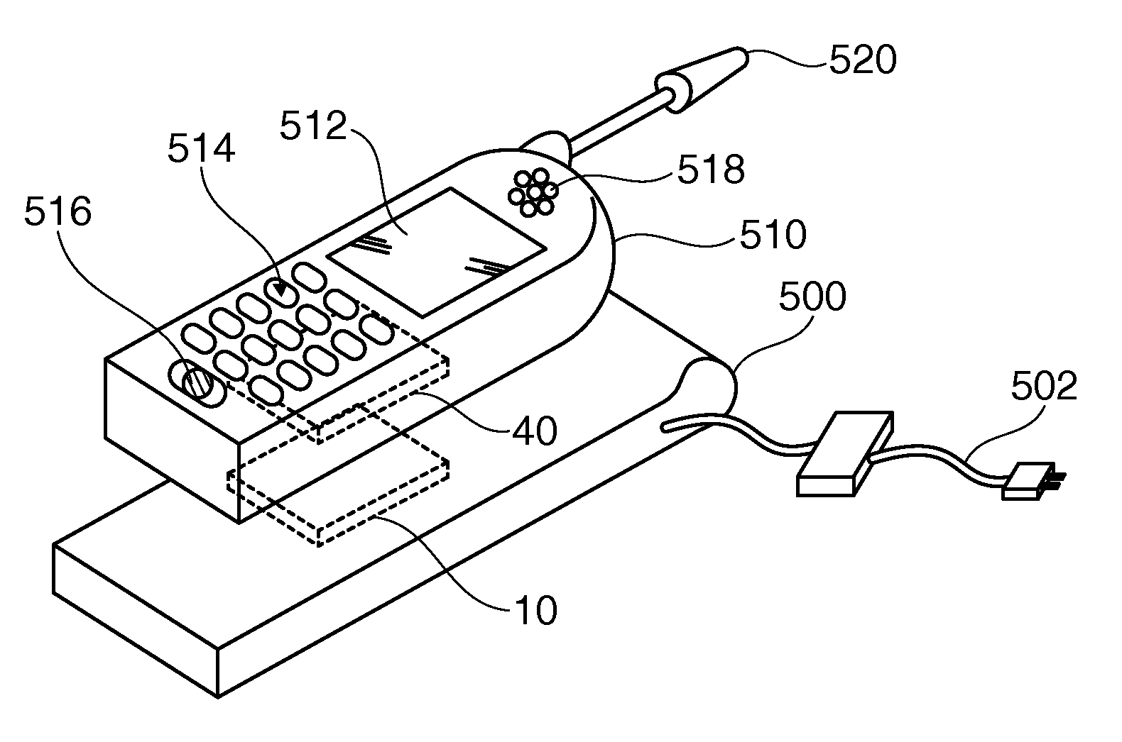
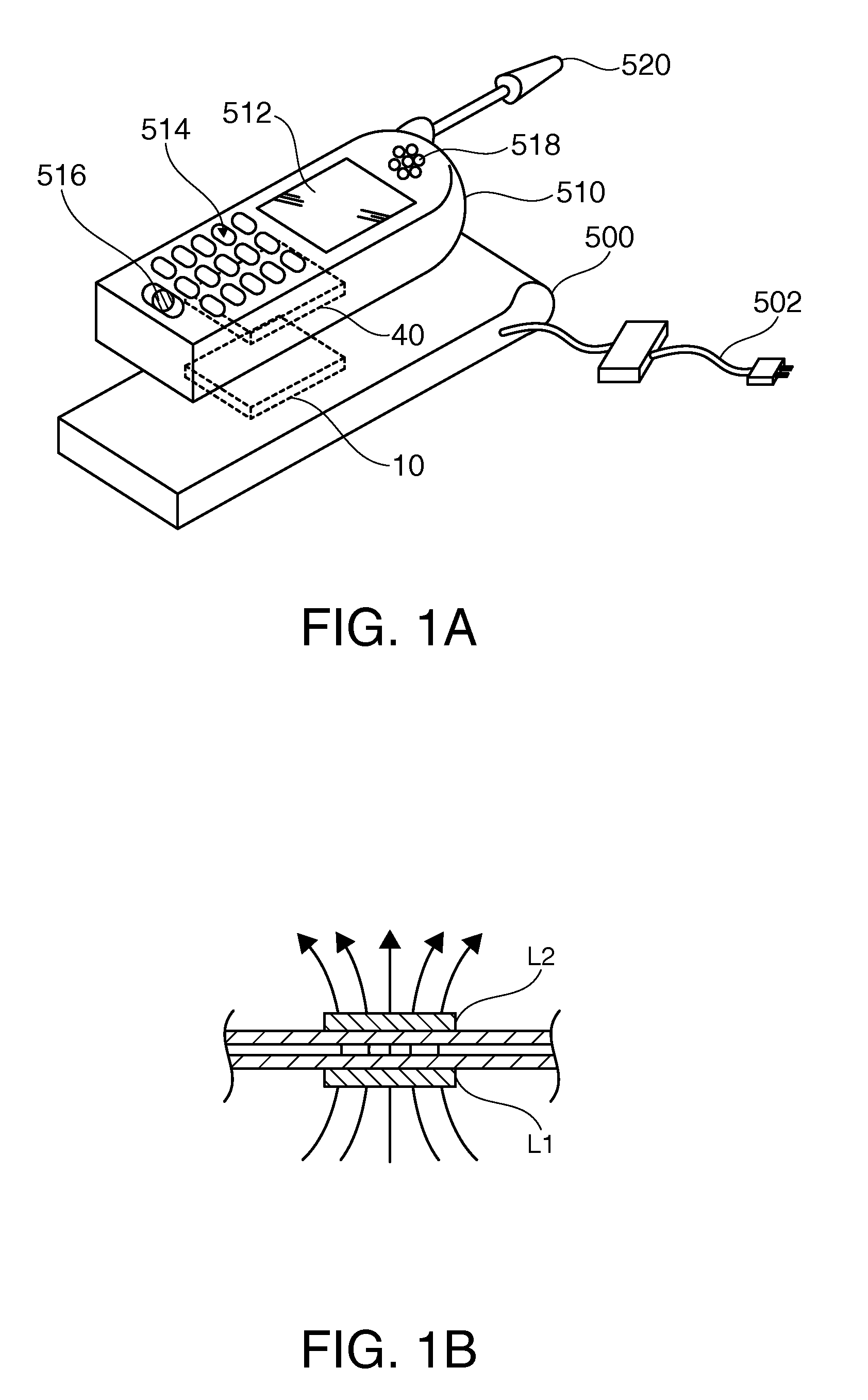
[0046]FIG. 1 (A) shows an example of an electronic instrument to which a contactless power transmission method in accordance with an embodiment is applied. A charger 500 (cradle), one of electronic instruments on the power transmission side, has a power transmission device 10. A portable telephone 510, one of electronic instruments on the power reception side, has a power reception device 40. Also, the portable telephone 510 includes a display section 512 such as an LCD, an operation section 514 composed of buttons and the like, a microphone 516 (a sound input section), and a s...


PUM


Abstract

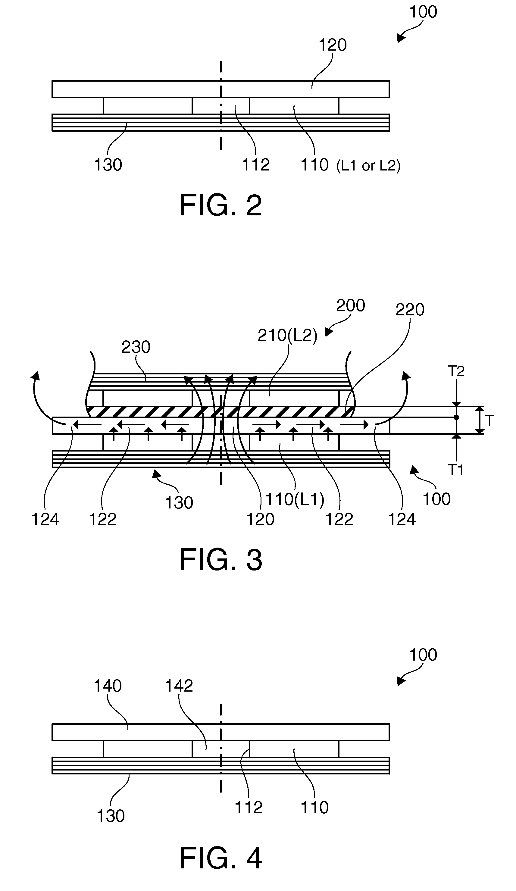
To provide coil units, electronic instruments and the like, which can radiate heat generated in a coil into a space outside a protective member, while the number of components does not increase.A coil unit 100 has a coil 110, and a protective member 120 that contacts a transmission surface of the coil 110 and covers at least the side of the transmission surface of the coil 110. The protective member 120 is composed of a resin material with an inorganic material added therein. The protective member 120 is also used as a heat radiation plate that dissipates heat generated in the coil 110 and radiates the heat.

Description

[0001]The present application claims priority based on Japanese Patent Application 2009-092820 filed Apr. 7, 2009, and the application is herein incorporated in the present specification.TECHNICAL FIELD[0002]The present invention relates to coil units and electronic instrument used for contactless power transmission and the like.TECHNOLOGICAL BACKGROUND[0003]Contactless power transmission that uses electromagnetic induction to enable power transmission without contacts between metal portions is known. As application examples of this contactless power transmission, charging of portable telephones and charging household appliances (e.g., cordless telephone handsets), and the like have been proposed.[0004]In contactless power transmission, the housing of each of a power transmission device and a power reception device is made of non-metal material such as plastics, such that a magnetic flux from a primary coil within the power transmission device can be effectively transmitted to a sec...

Claims


Application Information

Patent Timeline
IPC IPC(8): H02J17/00H01F27/28H01F27/08H02J7/00H01F38/14
CPCH01F27/2876H01F38/14H02J50/10
Inventor KONDO, YOICHIROSOGABE, HARUHIKOOKADA, HIROFUMI
Owner SEIKO EPSON CORP
Learn More