Smart meter cover with integral untethered antenna elements for ami communications

a technology of integrated antenna elements and smart meters, applied in waveguide devices, instruments, sustainable buildings, etc., can solve problems such as degrading the overall radio frequency system performance, and achieve the effect of reducing radio frequency coupling

Active Publication Date: 2010-10-07
RF SAVVY TECH
View PDF6 Cites 77 Cited by
  • Summary
  • Abstract
  • Description
  • Claims
  • Application Information

AI Technical Summary

Benefits of technology

[0018]It is another object of the present invention to address the shortcomings in, and improve upon, the above-described prior art of wireless automated meter reading and automated metering infrastructure embedded antennas by moving the antenna further away from the meter body and mounting a portion of the resonant structure of the antenna on the inside of the front cover of the meter. (As used herein, a “portion of” shall mean either a part of or the whole of the recited structure.) In this placement and configuration the antenna performance is least affected by the noise generated by the meter electronics and minimizes radio frequency coupling back to the radio receiver.
[0019]It is another object of the present invention to eliminate the need for the expensive discrete coaxial cable feed and radio or microwave frequency connector between a radio, microwave, or modular connectorized modem and the antenna which several of the above prior arts rely upon.

Problems solved by technology

However, such embedded antenna designs are taught in other references, such as U.S. Pat. No. 7,196,673, which explains that such designs degrade overall radio frequency system performance due to the proximity of the antennas to the noise sources within the meter.
In each of the aforementioned references there is an obvious effort to maximize the distance between the antenna and the meter electronic circuits, because the meter electronic circuits are a source of noise due to the mutual coupling into the antenna.

Method used


Image

  • Smart meter cover with integral untethered antenna elements for ami communications
  • Smart meter cover with integral untethered antenna elements for ami communications
  • Smart meter cover with integral untethered antenna elements for ami communications

Examples


Embodiment Construction

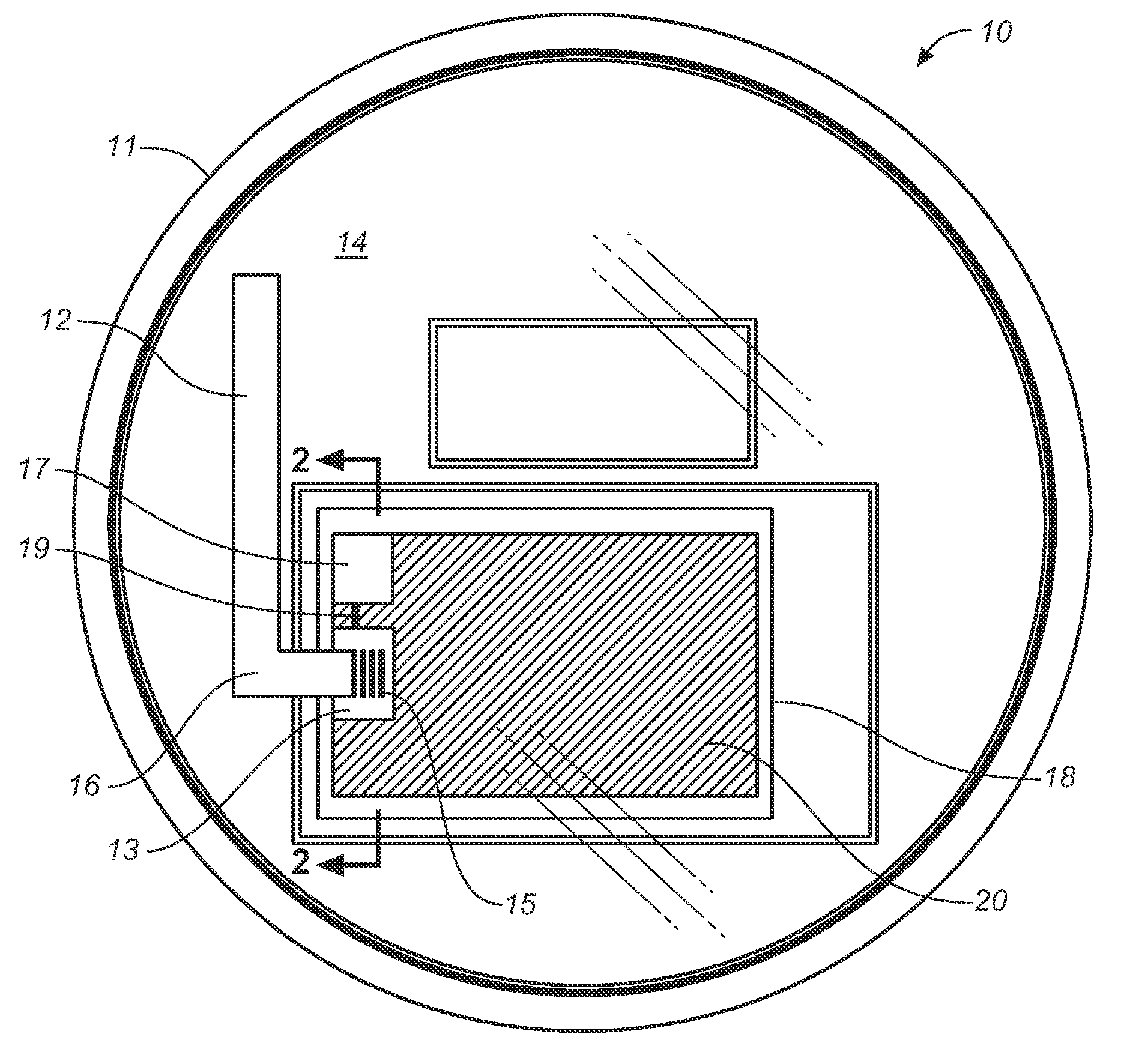
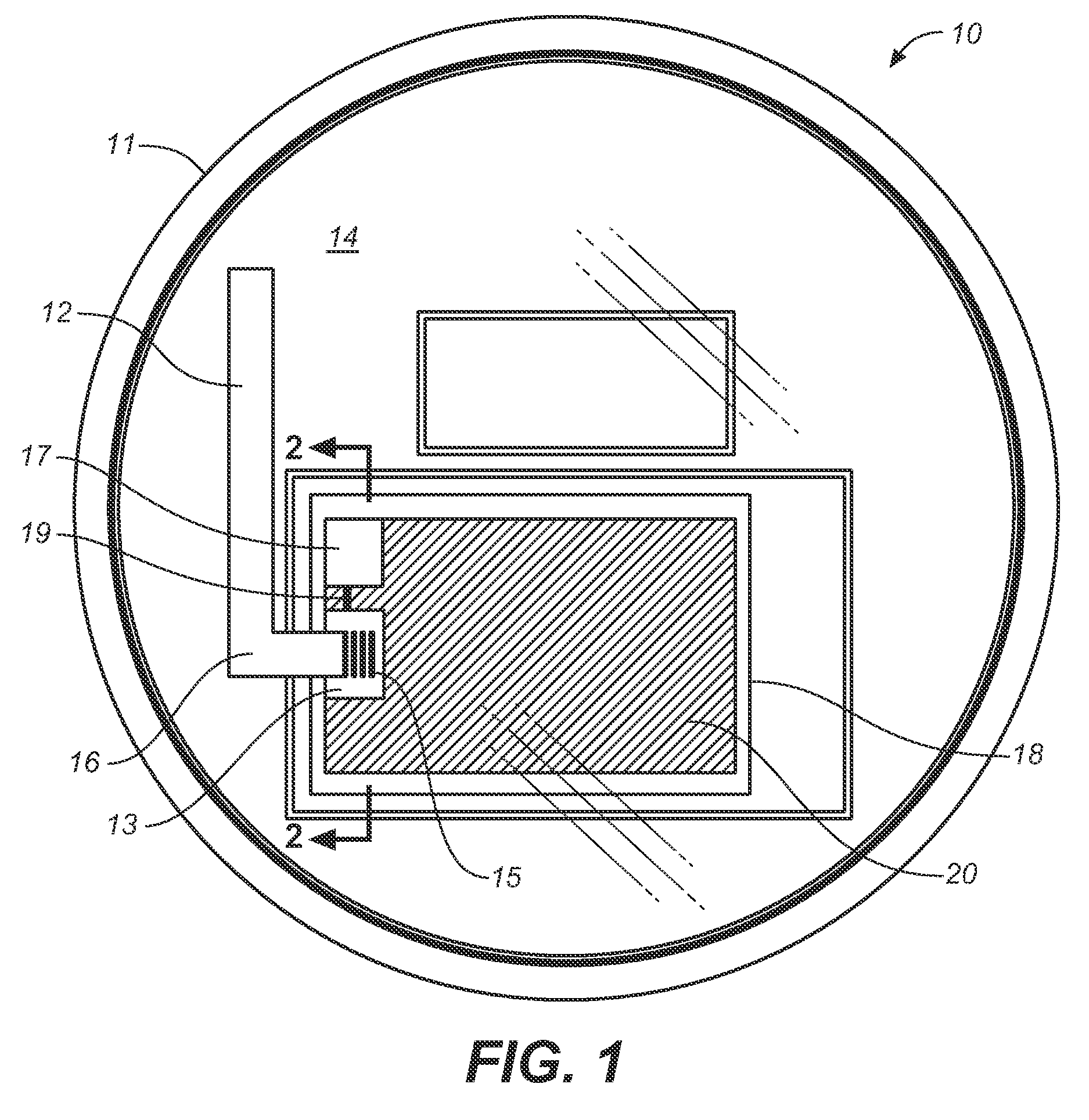
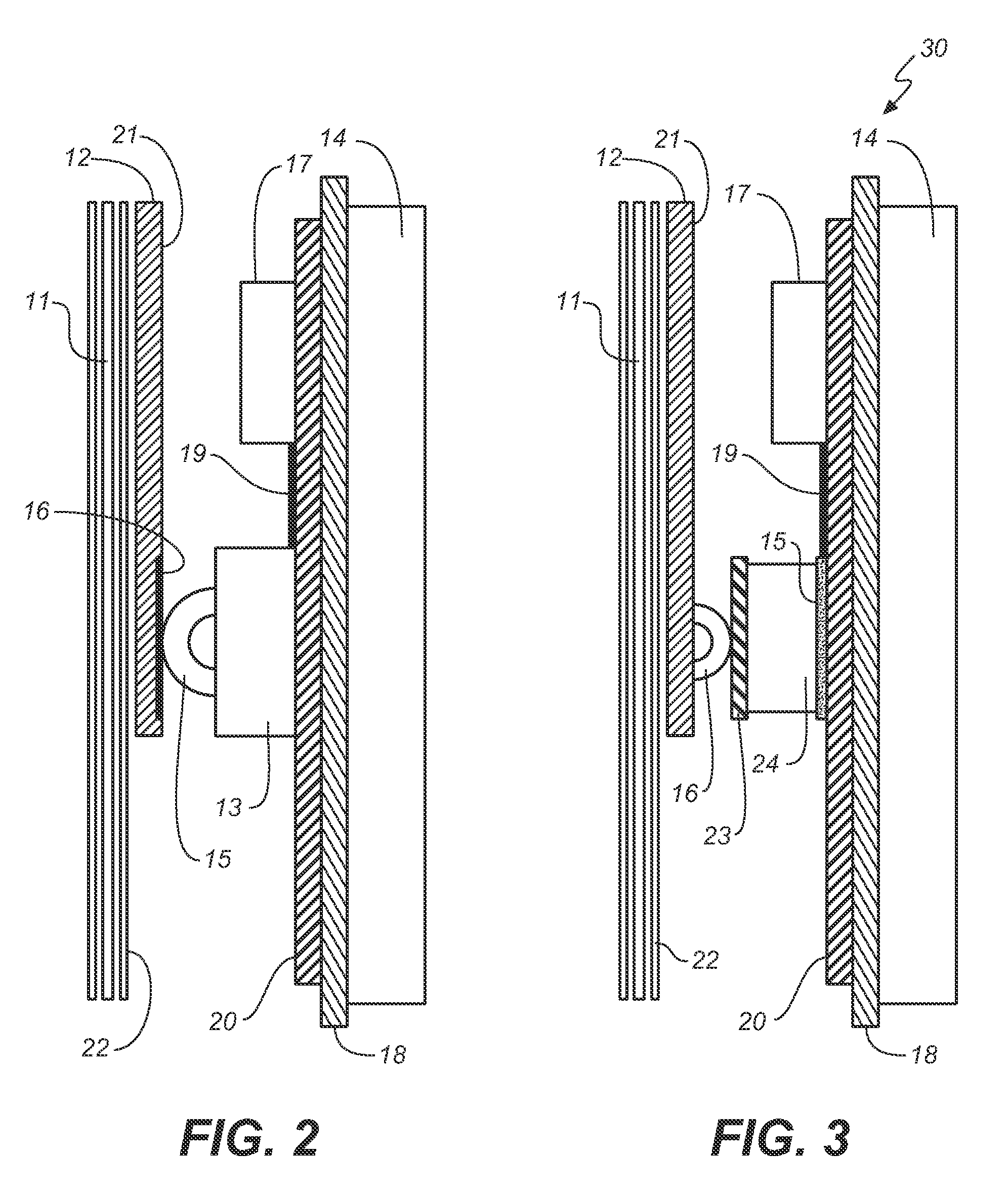
[0040]Referring first to FIGS. 1 and 2, wherein like reference numerals refer to like components in the various views, there is illustrated therein a new and improved embedded antenna entirely contained within the confines of a dielectric cover of an electric utility meter, the first preferred embodiment of which is generally denominated 10 herein. The inventive apparatus comprises an embedded antenna 12 that enables a multiplicity of untethered integral antenna elements and topologies to be located within and on the inner front cover of a replacement dielectric cover 11 of a utility meter. The structure of the antenna 12 is created by permanently forming the metal stamped antenna elements into the dielectric cover 11 using an insert-mold, molded interconnect, or heat staking manufacturing process to create a single-piece component that directly replaces the original dielectric cover with one containing an antenna 12 having integral antenna elements.

[0041]In the first preferred embo...


PUM

PropertyMeasurementUnit
dielectric constantaaaaaaaaaa

Abstract

Method and apparatus for mounting and locating untethered embedded antenna elements in the dielectric cover of electric utility meters configured for but not limited to wireless remote one way or two way radio communications for automated metering applications such as remote meter reading, remote connect/disconnect, home area networking, meter equipment firmware downloads, load management or locations based services. A multiplicity of untethered integral antenna elements and topologies may be located within a replacement dielectric cover for a direct-connect cable free or cable connection to a radio or microwave modem. Also described is a method and apparatus for retro-fitting the antenna elements on the inner face of an existing utility meter dielectric cover.

Description

CROSS REFERENCES TO RELATED APPLICATIONS[0001]The present application claims the benefit of U.S. Provisional Patent Application Ser. Numbers 61 / 167,157 and 61 / 241,400, filed Apr. 7, 2009 and Sep. 11, 2009, respectively.STATEMENT REGARDING FEDERALLY SPONSORED RESEARCH OR DEVELOPMENT[0002]Not applicable.THE NAMES OR PARTIES TO A JOINT RESEARCH AGREEMENT[0003]Not applicable.INCORPORATION-BY-REFERENCE OF MATERIAL SUBMITTED ON A COMPACT DISC[0004]Not applicable.SEQUENCE LISTING[0005]Not applicable.BACKGROUND OF THE INVENTION[0006]1. Field of the Invention[0007]The present invention relates generally to antennas for utility meters. More specifically the present invention relates to an untethered antenna for use in electricity utility meters configured for but not limited to wireless remote one way or two way communications for automated metering infrastructure (AMI) applications such as remote meter reading, remote connect / disconnect, home area networking, meter equipment firmware downloa...

Claims


Application Information

Patent Timeline
Patent Type & Authority Applications(United States)
IPC IPC(8): G08C15/06H01Q1/24H01Q1/42H01P11/00
CPCG01D4/002G01D4/008H01Q1/2233Y02B90/247Y10T29/49018Y02B90/241Y02B90/246Y04S20/32Y04S20/42Y04S20/50Y02B90/20Y04S20/30
Inventor SMITH, NORMAN JAMES
Owner RF SAVVY TECH
Why Eureka
Try Eureka