Display device and electronic apparatus equipped with the same

a technology of electronic equipment and display device, which is applied in the direction of static indicating device, optical radiation measurement, instruments, etc., can solve the problems of inaccurate detection of ambient light and drawbacks of conventional display device, and achieve the effect of accurate detection of ambient ligh

Inactive Publication Date: 2010-10-07
INNOLUX CORP
View PDF7 Cites 47 Cited by
  • Summary
  • Abstract
  • Description
  • Claims
  • Application Information

AI Technical Summary

Benefits of technology

[0004]An object of the present invention provides a display device and an electronic apparatus having such display device in order to accurately detect the ambient light.
[0006]The use of the color filter layer can reduce the influence of the light reflected by the black matrix, so that the accuracy of detecting the ambient light is enhanced.
[0008]Since the no special fabricating process is required to form the color filter layer on the black matrix, the fabricating cost is reduced.
[0011]As such, the use of the compensating sensor can increase the accuracy of detecting the ambient light.
[0013]The present invention provides a display device and an electronic apparatus equipped with the display device in order to accurately detect the ambient light.

Problems solved by technology

The conventional display device, however, still has some drawbacks.
For example, due to light reflection within the displaying module of the display device, the ambient light fails to be accurately detected.

Method used


Image

  • Display device and electronic apparatus equipped with the same
  • Display device and electronic apparatus equipped with the same
  • Display device and electronic apparatus equipped with the same

Examples


first embodiment

[0036]FIGS. 3A and 3B are cross-sectional views illustrating two types of display panels of the display devices according to the present invention.

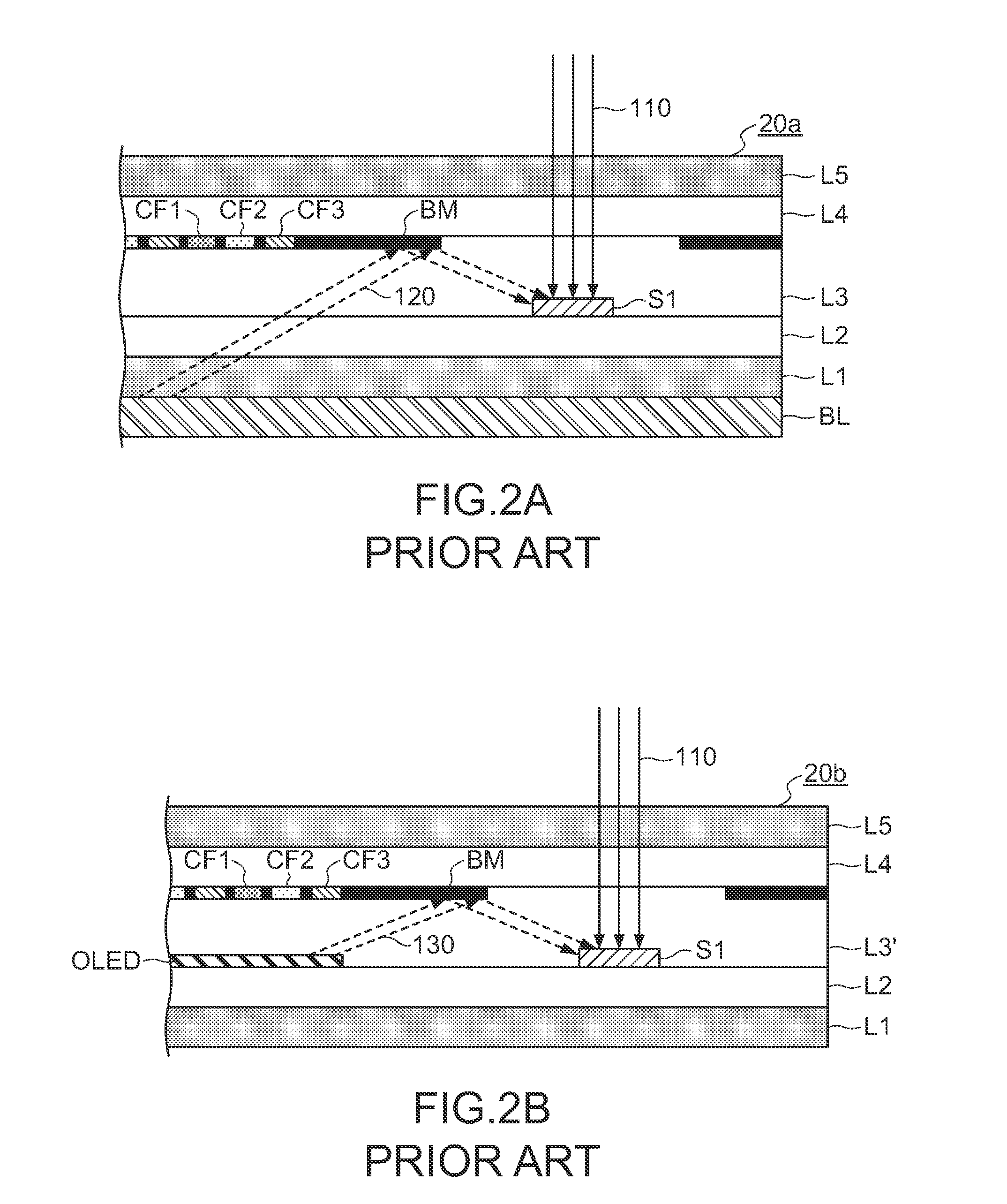
[0037]FIG. 3A is a schematic cross-sectional view illustrating a display panel of a liquid crystal display (LCD) device. In comparison with the display panel 20a of FIG. 2A, layered color filter layers 32 and 33 are deposited on the surface of the black matrix BM of the display panel 30a of FIG. 3A. In views of cost-effectiveness, the color filter layers 32 and 33 are produced by the same process of fabricating the color filter layers CF1, CF2 and CF3, which are arranged between the grids of the black matrix BM. The color filter layers 32 and 33 have different colors. The colors of the color filter layers 32 and 33 are selected according to the spectrum of the light which is supposed not to be detected by but becomes accessible to the external light sensor S1 as reflected by the black matrix BM.

[0038]For preventing the backlight, which is...

second embodiment

[0056]FIGS. 8A and 8B are cross-sectional views illustrating two types of display panels of the display devices according to the present invention.

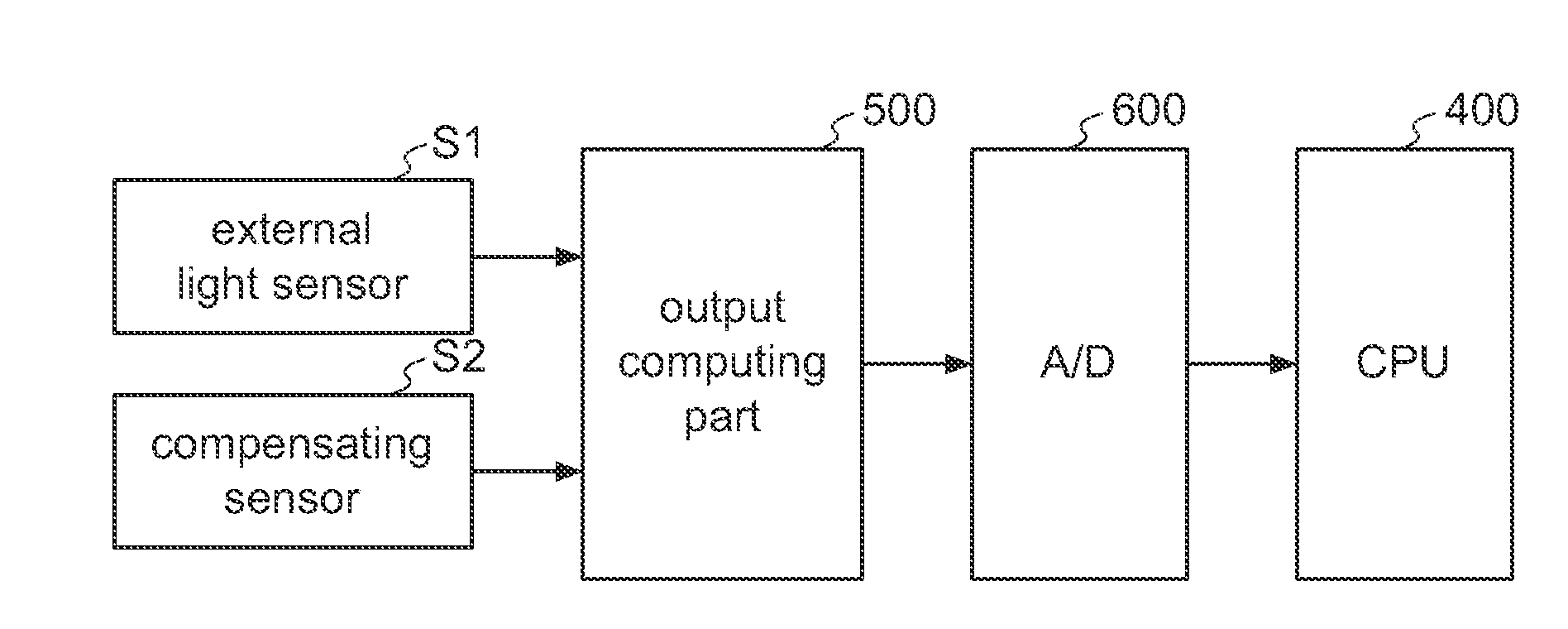
[0057]FIG. 8A is a schematic cross-sectional view illustrating a display panel of a liquid crystal display (LCD) device. The configurations of the display panel 40a of FIG. 8A are substantially identical to those of the display panel 30a of FIG. 3A, except that a compensating sensor S2 is disposed on the interface between the first glass substrate L2 and the display layer L3 and arranged in a region where the external light 110 passing through the second glass substrate L4 is hindered by the black matrix BM. FIG. 8B is a schematic cross-sectional view illustrating a display panel of an organic light emitting display (OLED) device. The configurations of the display panel 40b of FIG. 8B are substantially identical to those of the display panel 30b of FIG. 3B, except that a compensating sensor S2 is disposed on the interface between the firs...


PUM


Abstract

A display device includes a display layer, a first glass substrate, a second glass substrate, an external light sensor, a black matrix and a color filter layer. The display layer has polarizing or light-emitting display components, which are arranged in a matrix. The first glass substrate and the second glass substrate are respectively disposed over and under the display layer. The external light sensor is disposed on an interface between the first glass substrate and the display layer for detecting an external light passing through the second glass substrate incident to the external light sensor. The black matrix is disposed on an interface between the second glass substrate and the display layer. The external light passing through the second glass substrate is sheltered by the black matrix. The color filter layer is deposited on the black matrix and has a specified transmittance spectrum property.

Description

FIELD OF THE INVENTION[0001]The present invention relates to a display device having a display panel for detecting the ambient light. The present invention also relates to an electronic apparatus equipped with such a display device.BACKGROUND OF THE INVENTION[0002]Nowadays, the display device of an electronic apparatus (especially the mobile apparatus used in the outdoor environment, for example, a vehicular navigation apparatus, a mobile phone, or the like) usually has a luminance adjustable function for adjusting the luminance according to the brightness of the ambient light. For example, PCT Invention Patent Application WO 99 / 022962 disclosed a display system. In the display system, the ambient light is detected by an ambient light sensor, and the luminance of the display is adjusted by a brightness controller according to the brightness of the ambient light. By means of this function, the luminance of the display is increased when the electronic apparatus is used in a bright env...

Claims


Application Information

Patent Timeline
Patent Type & Authority Applications(United States)
IPC IPC(8): G09G3/36G09G5/00
CPCG01J1/02G01J1/0214G01J1/0219G01J1/42G02F1/133512H01L27/3269G02F2201/58G09G3/20G09G2320/041G09G2320/0626G09G2360/144G02F1/133514H10K59/13
Inventor HASHIMOTO, KAZUYUKI
Owner INNOLUX CORP
Why Eureka
Try Eureka