Image coding method, image decoding method, image coding apparatus, image decoding apparatus, system, program, and integrated circuit

a coding method and image technology, applied in the field of image coding method, image coding method image coding apparatus, etc., can solve the problem that blocking artifacts has a negative effect on human visual perception, and achieve the effect of improving coding efficiency

Inactive Publication Date: 2010-10-07
PANASONIC CORP
View PDF5 Cites 71 Cited by
  • Summary
  • Abstract
  • Description
  • Claims
  • Application Information

AI Technical Summary

Benefits of technology

[0071]The present invention improves the coding efficiency and enables an adaptive filter process by reducing the frequency of calculation of the first correlation data transferred from an image coding apparatus to an image decoding apparatus and more frequently calculating the second correlation data that can be calculated by both the video coding apparatus and the video decoding apparatus.

Problems solved by technology

Due to coding per block, the superposed noise often has blocking characteristics, which result, in particular for strong quantization, in visible block boundaries in the decoded image.
Such blocking artifacts have a negative effect upon human visual perception.

Method used


Image

  • Image coding method, image decoding method, image coding apparatus, image decoding apparatus, system, program, and integrated circuit
  • Image coding method, image decoding method, image coding apparatus, image decoding apparatus, system, program, and integrated circuit
  • Image coding method, image decoding method, image coding apparatus, image decoding apparatus, system, program, and integrated circuit

Examples


embodiment 1

[0104]FIG. 5A schematically illustrates a video coding apparatus 500 according to Embodiment 1 of the present invention. Furthermore, FIG. 5B shows a flowchart of operations of the video coding apparatus 500. Although the following description shows an example of a video signal to be processed, other signals (for example, still images) may be provided, not limited to the video signal. As illustrated in FIG. 5A, the video coding apparatus 500 includes a coding unit 510, a decoding unit 520, a filter design unit 530, and a filter 540.

[0105]The coding unit 510 codes an input signal (also referred to as “a signal to be coded” and follows the same hereinafter). The input signals typically are signals composing a picture (frame). Here, “to be coded” means, for example, processing for quantizing the input signals. More specifically, the processing indicates generating a prediction error signal by subtracting a prediction signal from the input signals, DCT transforming the prediction error ...

embodiment 2

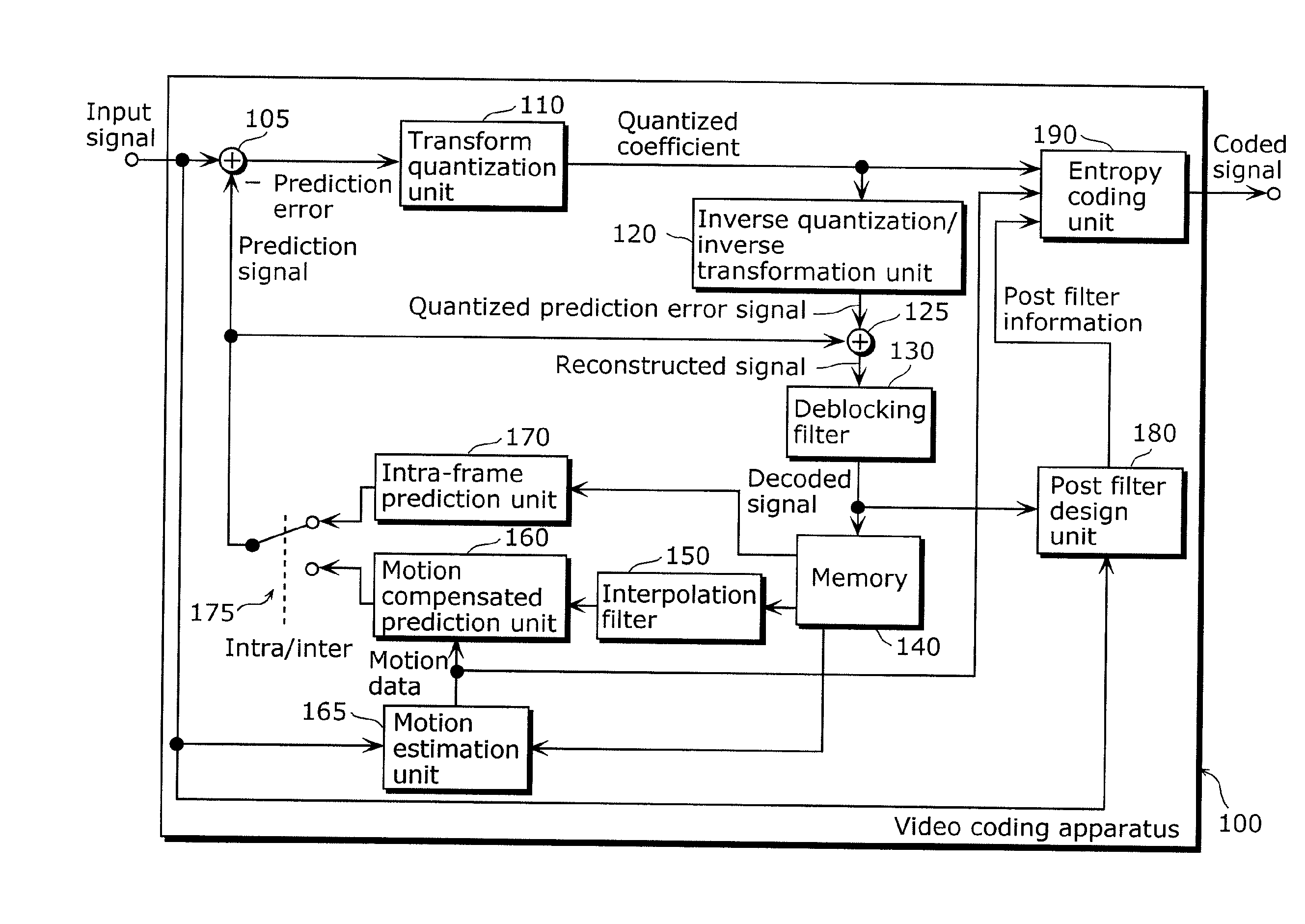
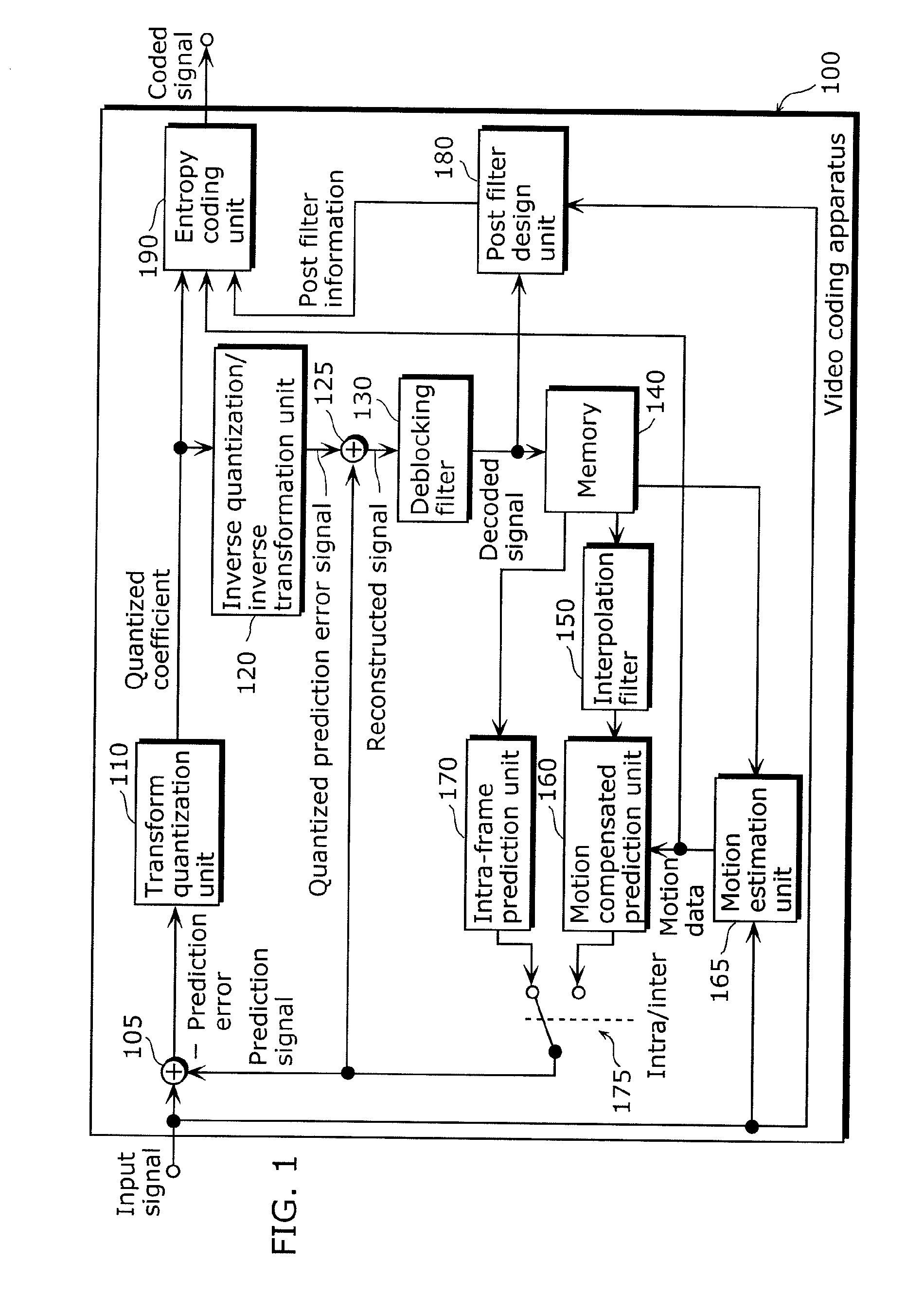
[0211]FIG. 10 illustrates a video coding apparatus 600 modified based on the H.264 / AVC video coding standard, according to Embodiment 2 in the present invention.

[0212]As illustrated in FIG. 10, the video coding apparatus 600 includes a subtractor 105, a transform quantization unit 110, an inverse quantization / inverse transformation unit 120, an adder 125, a deblocking filter 130, an entropy coding unit 190, and a predicted block generation unit (not illustrated). The video coding apparatus 600 subdivides a signal to be coded into blocks, and sequentially codes the blocks. The signal to be coded represents an image.

[0213]The subtractor 105 subtracts a predicted block (prediction signal) from a block to be coded (input signal) to generate a prediction error signal. The transform quantization unit 110 performs Discrete Cosine Transformation (DCT) on the prediction error signal, quantizes the DCT-transformed prediction error signal, and generates quantized coefficients. The entropy codi...

embodiment 3

[0232]According to further Embodiment 3 in the present invention, a video coding apparatus 800 and a video decoding apparatus 900 each with an interpolation filter are provided. FIG. 12 illustrates the video coding apparatus 800 including an interpolation filter and design unit 850. The description of the commonalities with each of Embodiments will be omitted, and the differences will be mainly described hereinafter.

[0233]The interpolation filter and design unit 850 operates and includes the same configuration, as the filter design unit 530 described with reference to FIG. 5A. Furthermore, the interpolation filter and design unit 850 operates and includes the same configuration, as the interpolation filter 150 described with reference to FIG. 10. In other words, the interpolation filter and design unit 850 performs interpolation filtering on a decoded signal, and calculates a filter coefficient used by itself.

[0234]The locally determined correlation data determined by the interpolat...


PUM


Abstract

An image coding method includes: quantizing a signal to be coded to determine a quantized coefficient (S11); inverse quantizing the quantized coefficient to generate a decoded signal (S12); subdividing the decoded signal into image areas (S13); estimating (i) first correlation data for each area larger than one of the image areas determined in the subdividing, and (ii) second correlation data for each of the image areas determined in the subdividing, the first correlation data indicating a correlation between the signal to be coded and the decoded signal, and the second correlation data indicating an autocorrelation of the decoded signal (S14); calculating a filter coefficient using the first and second correlation data for each of the image areas (S15); filtering the decoded signal for each of the image areas, using the filter coefficient calculated in the calculating; and providing only the first correlation data from the first and second correlation data.

Description

TECHNICAL FIELD[0001]The present invention relates to a method and an apparatus for coding and decoding video using adaptive filters for filtering video signals.BACKGROUND ART[0002]At present, the majority of standardized video coding algorithms are based on hybrid video coding. Hybrid video coding methods typically combine several different lossless and lossy compression schemes in order to achieve a desired compression gain. Hybrid video coding is also the basis for ITU-T standards (H.26x standards such as H.261 and H.263) as well as ISO / IEC standards (MPEG-X standards such as MPEG-1, MPEG-2, and MPEG-4). The most recent and advanced video coding standard is currently the standard denoted as H.264 / MPEG-4 advanced video coding (AVC) which is a result of standardization efforts by joint video team (JVT), a joint team of ITU-T and ISO / IEC MPEG groups.[0003]A video signal input to a video coding apparatus is a sequence of images called frames (or pictures), and each frame is a two-dim...

Claims


Application Information

Patent Timeline
Patent Type & Authority Applications(United States)
IPC IPC(8): H04N7/26
CPCH04N19/147H04N19/172H04N19/46H04N19/61H04N19/86H04N19/157H04N19/17H04N19/80H04N19/82H04N19/117
Inventor NARROSCHKE, MATTHIASWITTMANN, STEFFENWEDI, THOMASSHIBAHARA, YOUJI
Owner PANASONIC CORP
Why Eureka
Try Eureka