Vacuum assisted surgical dissection tools

a technology of surgical dissection and vacuum, which is applied in the field of vacuum devices for minimally invasive thoracic surgery, can solve the problems of difficult angle of approach the surgeon must use through the opening, and achieve the effect of improving the accuracy of surgical dissection and reducing the difficulty of surgery

Active Publication Date: 2010-10-07
TYCO HEALTHCARE GRP LP
View PDF26 Cites 33 Cited by
  • Summary
  • Abstract
  • Description
  • Claims
  • Application Information

AI Technical Summary

Problems solved by technology

Also, since the internal mammary arteries are attached to the thoracic cavity wall, the angle of approach the surgeon must use through

Method used


Image

  • Vacuum assisted surgical dissection tools
  • Vacuum assisted surgical dissection tools
  • Vacuum assisted surgical dissection tools

Examples


Embodiment Construction

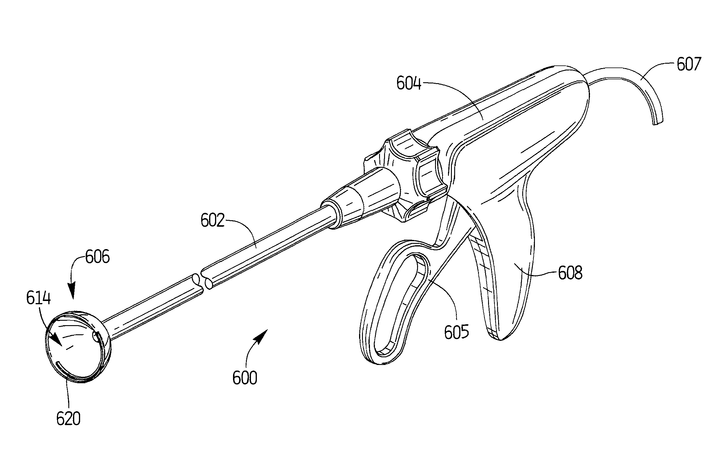
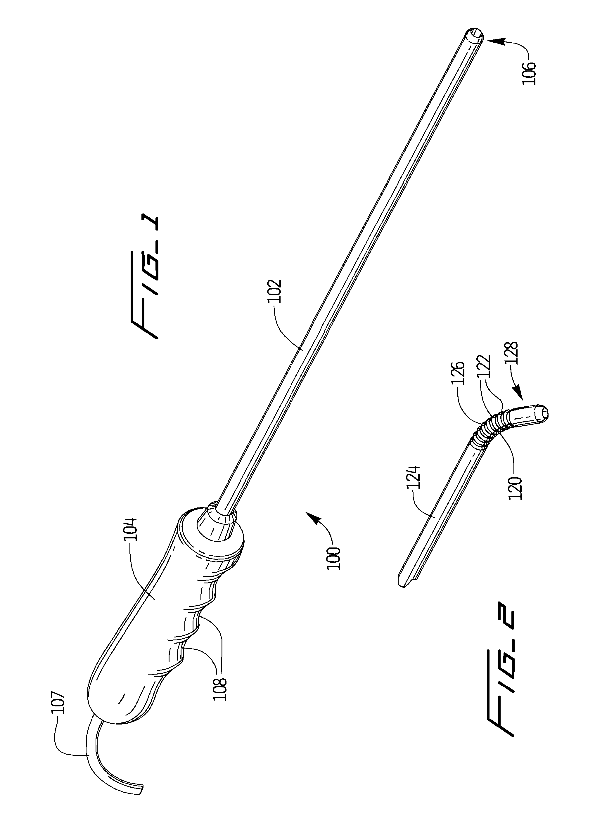
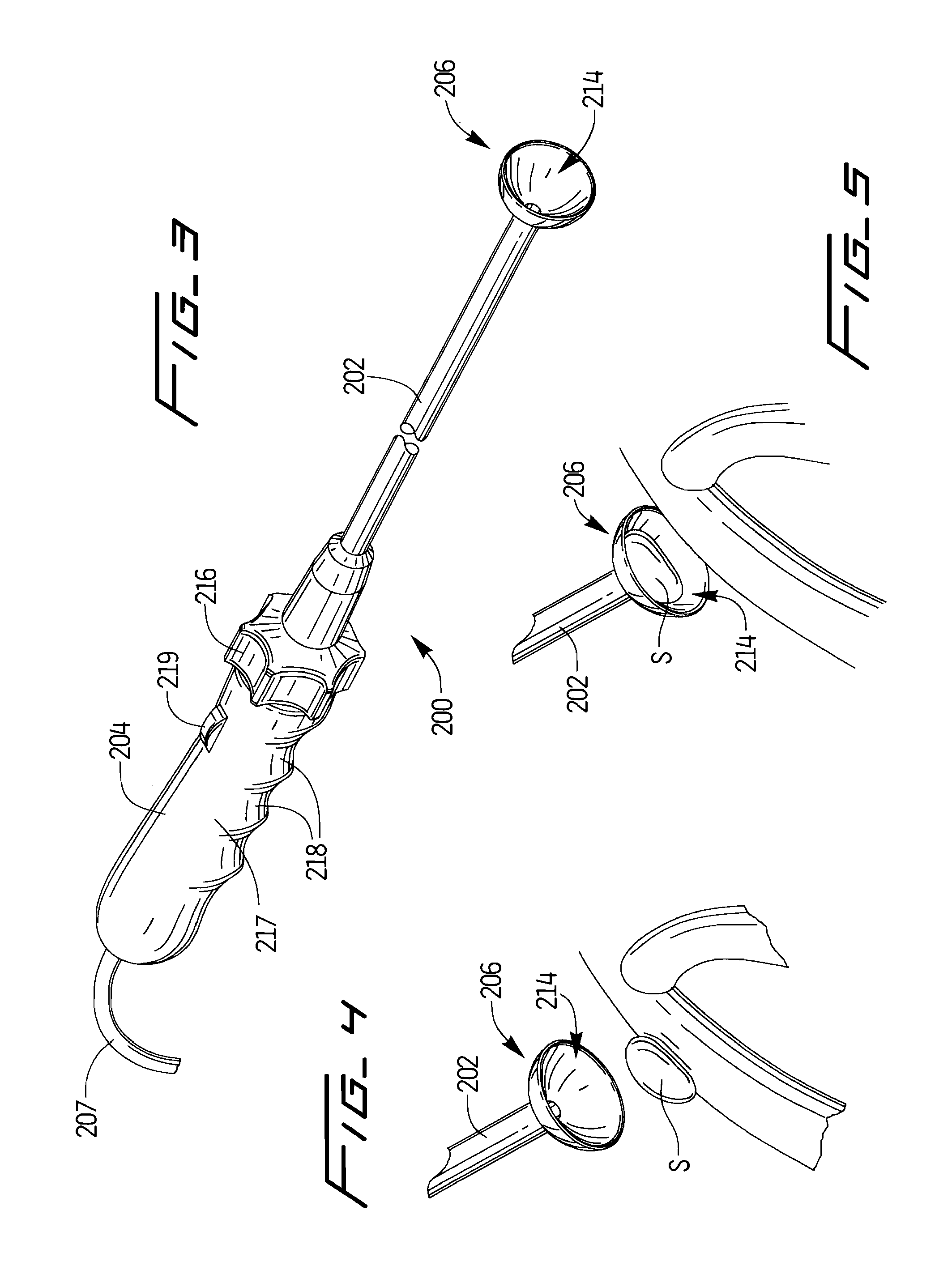
[0031]The present disclosure relates to vacuum assisted devices. In some embodiments, the vacuum is used for dissection and specimen retrieval, such as in FIGS. 1-5. These suction devices enable a surgeon to have controlled tension during delicate dissection. In other embodiments, a cutting blade is used to sever the tissue adjacent the specimen and a vacuum is used for specimen retrieval, such as in FIGS. 6-17.

[0032]FIG. 1 illustrates a first embodiment of the device of the present disclosure, designated generally by reference numeral 100. Device 100 has an elongate tube or shaft 102 and a handle 104 attached at the proximal end thereof. The elongate tube 102 has a suction tip 106 disposed on the distal end. A vacuum tube 107 extends from the proximal end of the handle 104. The handle can have indentations 108 to enhance gripping by the clinician. The suction tip 106 is configured and dimensioned to vacuum a tumor specimen into the distal end thereof. This embodiment enables a surg...


PUM


Abstract

A surgical device comprising a handle, an elongated tube extending distally from the handle, and a suction tip at a distal end portion of the elongated tube. The suction tip has a cavity formed therein. A cutting blade is positioned at least partially within the cavity and rotatable across the cavity to sever tissue, the cavity dimensioned to receive the severed tissue for removal from a patient's body.

Description

[0001]This application claims priority from U.S. Provisional Application No. 61 / 107,752, filed Oct. 23, 2008, the entire contents of which are incorporated herein by reference.BACKGROUND [0002]1. Technical Field[0003]This application relates to a device for minimally invasive surgery and more particularly to a vacuum device for minimally invasive thoracic surgery.[0004]2. Description of the Related Art[0005]In recent years, new methods of access into the thoracic cavity have been developed in order to perform some of the surgical procedures done before through a median sternotomy. One minimally invasive method is called a mini-thoracotomy and involves access through an incision running intercostally (between two ribs) of the left chest wall. A surgical retractor is used as for the median sternotomy, but in this case, the superior and inferior rib cages of the left chest are spread apart about two inches, thus resulting in much less overall trauma to the bones, muscles, and other tis...

Claims


Application Information

Patent Timeline
IPC IPC(8): A61B17/3205A61B10/04
CPCA61B10/06A61B2017/32004A61B2017/308A61B17/320016A61B10/0283A61B17/32002A61B18/00A61B2017/00367A61B2017/00561A61B2017/320064A61B2018/00595
Inventor RACENET, DANYEL J.WELLS, TIMOTHY N.BENNETT, STEVEN L.ELACHCHABI, AMINBETTUCHI, MICHAEL J.HEMBER, MILES WILLIAM NOEL
Owner TYCO HEALTHCARE GRP LP
Why Eureka
Try Eureka