Apparatus for vacuum-assisted irrigation and drainage of a body cavity

a technology of vacuum-assisted irrigation and apparatus, which is applied in the direction of suction irrigation system, suction device, other medical devices, etc., can solve the problems of inability to fully discharge, interrupt the body's natural defense mechanism, and increase the risk of ventilator-associated pneumonia (vap)

Inactive Publication Date: 2005-09-08
BOEHRINGER LABORATORIES
View PDF4 Cites 75 Cited by
  • Summary
  • Abstract
  • Description
  • Claims
  • Application Information

AI Technical Summary

Benefits of technology

[0005] In view of the shortcomings of conventional systems and methods, a system to administer a liquid agent into a body cavity of a patient for use with a vacuum source is provided.

Problems solved by technology

It has been known that patients on mechanical ventilation are at increased risk of developing Ventilator Associated Pneumonia (VAP).
Additionally, the artificial airway is an imperfect barrier to bacteria colonies that inhabit the mouth, throat and stomach, and interrupts the body's natural defense mechanism.
Subglottic secretions that are encountered in the airway can be very thick and persistent and present a challenge for removal via the conventional passages in the artificial airways.
Adding additional lumens to artificial airways is not practical, because concern exists over the available space in the patient's throat.

Method used


Image

  • Apparatus for vacuum-assisted irrigation and drainage of a body cavity
  • Apparatus for vacuum-assisted irrigation and drainage of a body cavity
  • Apparatus for vacuum-assisted irrigation and drainage of a body cavity

Examples


Embodiment Construction

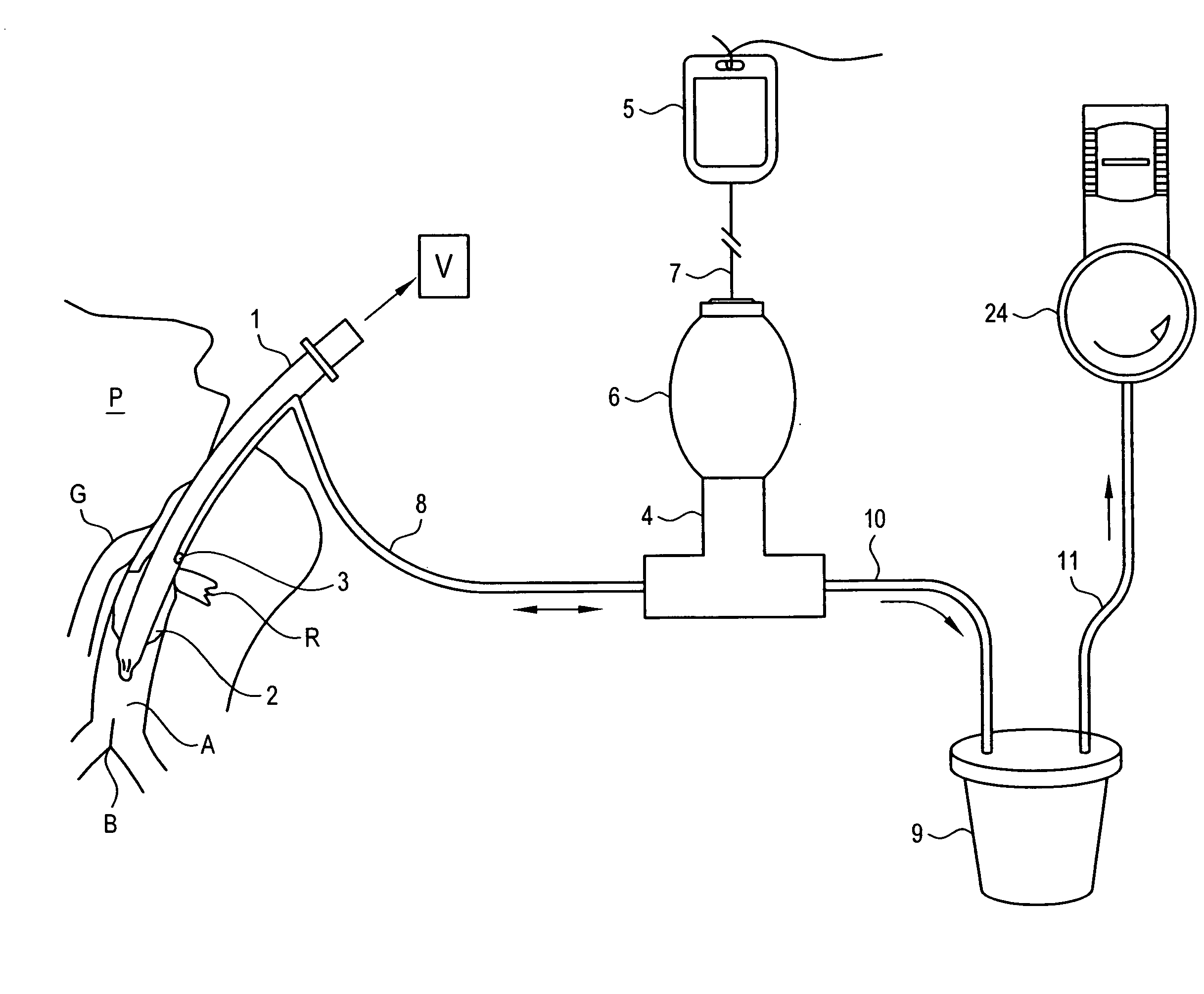
[0023]FIG. 1 illustrates a system according to an exemplary of the present invention. As shown in FIG. 1, patient P is mechanically ventilated by ventilation source V via a lumen, such as endotracheal tube 1. Endotracheal tube 1 is desirably placed in the trachea above the bronchial bifurcation B and below the glottis G. An inflatable balloon or cuff 2 is inflated to seal the breathing tube in the patient's airway A. The region R, defined by the space above the proximal end of the cuff and the glottis, refers to the subglottic space and is the area of attention for the exemplary device. Endotracheal tube 1 is a modified device and contains an aspiration port 3 used to evacuate the subglottic space. One type of endotracheal tube 1 that may be used is the HI-LO Evac ET Tube manufactured by TYCO Healthcare / Mallinkrodt of Hazelwood, Mo. Current use of the endotracheal tube involves either continuous or intermittent suction to remove the fluids that accumulate in the subglottic space.

[0...


PUM


Abstract

A system and method to administer a liquid agent into a body cavity of a patient is provided. One exemplary system comprises a lumen disposed into an airway of the patient and a valve assembly coupled to the lumen. The valve assembly comprises a body portion, a first port and a second port. A pump assembly for receiving the liquid agent is coupled to the valve assembly in a fluid tight relationship. The pump assembly provides the liquid to the lumen through the first port of the valve assembly. The liquid along with a portion of secretions generated by the patient are extracted through the lumen and flow out of said valve assembly through the second port for disposal responsive to a natural body function and/or a vacuum from a vacuum source. One exemplary method comprises the steps of disposing a lumen into the body cavity of the patient, the lumen comprising a fluid port; introducing the liquid agent into the body cavity through the fluid port; and extracting at least the liquid from the body cavity through the fluid port responsive to a natural body function and/or a vacuum from the vacuum source.

Description

CROSS REFERENCE TO RELATED APPLICATIONS [0001] This application claims the benefit of priority to U.S. Provisional Patent Application No. 60 / 549,973, filed on Mar. 4, 2004, the contents of which are incorporated in this application by reference. FIELD OF THE INVENTION [0002] This invention relates to devices and methods for irrigating and draining body cavities with vacuum. More specifically, this invention relates to applications where the irrigation and aspiration of body cavities of a patient, such as the subglotic region of a patient on mechanical ventilation can be a beneficial aid to reducing the risk of pneumonia acquired as a result of such mechanical ventilation. BACKGROUND OF THE INVENTION [0003] Critically ill patients often require life support in the form of mechanical ventilation. Ventilated patients receive an artificial airway in the form of an Endotracheal Tube or Tracheostomy Tube. The artificial airway is placed in the trachea and a distal cuff is inflated to seal...

Claims


Application Information

Patent Timeline
Patent Type & Authority Applications(United States)
IPC IPC(8): A61M31/00
CPCA61M1/0062A61M16/0463A61M2210/1078A61M2210/1039A61M2210/1053A61M2210/1032A61M1/772
Inventor KARPOWICZ, JOHNKLOCEK, KEVIN P.
Owner BOEHRINGER LABORATORIES
Why Eureka
Try Eureka