Surgical fluid management system with suction control

Inactive Publication Date: 2007-04-17
ETHICON INC
View PDF23 Cites 87 Cited by
  • Summary
  • Abstract
  • Description
  • Claims
  • Application Information

AI Technical Summary

Benefits of technology

[0003]The problems and disadvantages associated with conventional techniques and devices for controlling the volume of surgical fluid present in a cavity of the body during surgery are overcome by the present invention which includes a conduit to the cavity for conducting the surgical fluid therefrom

Problems solved by technology

During procedures of this type, the amount of irrigating liquid present in the patient's body must be

Method used


Image

  • Surgical fluid management system with suction control
  • Surgical fluid management system with suction control
  • Surgical fluid management system with suction control

Examples


Embodiment Construction

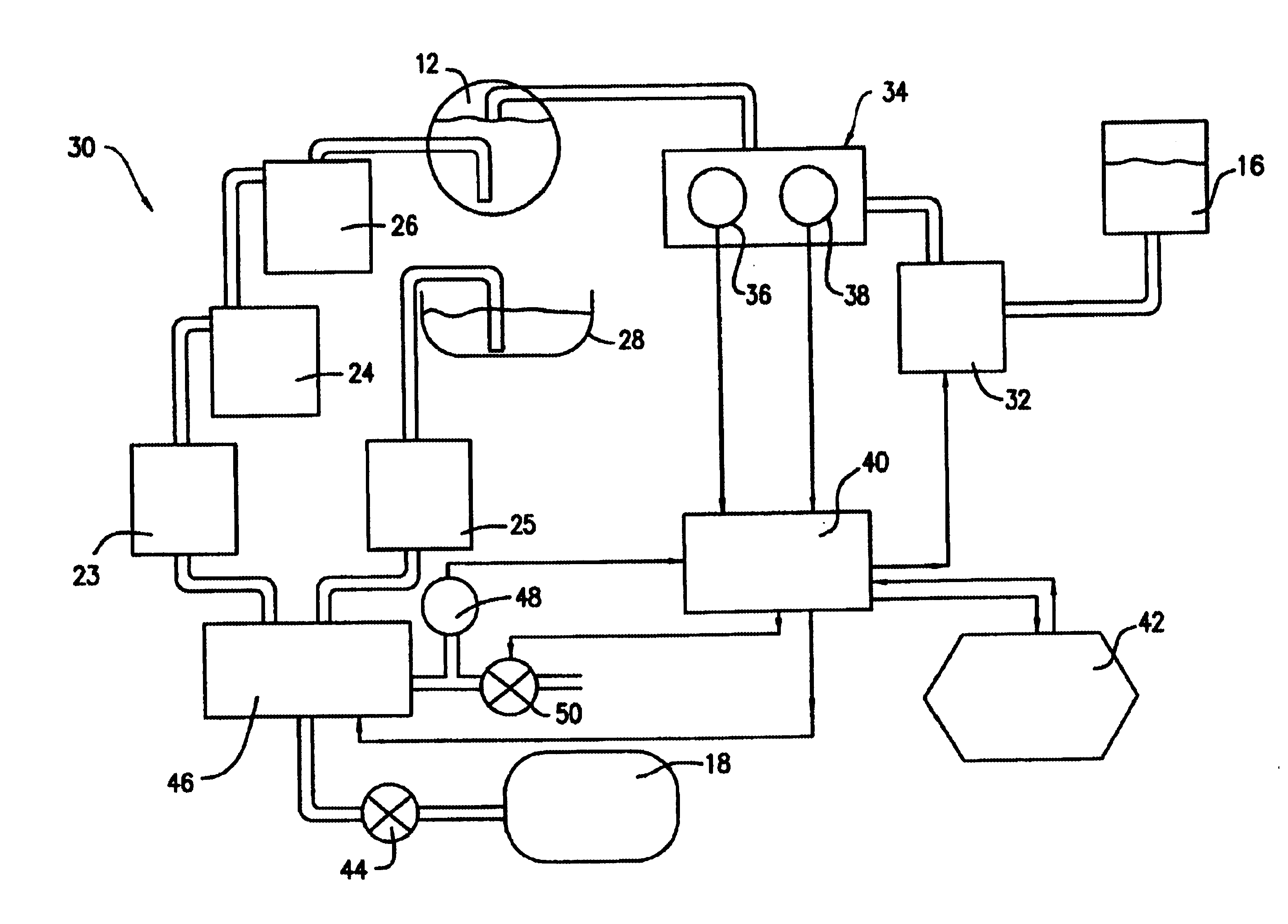
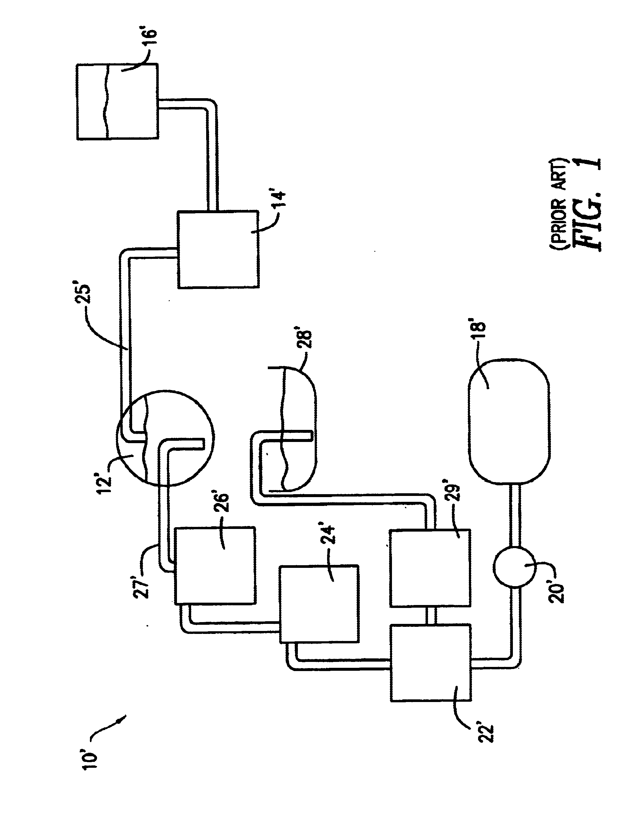
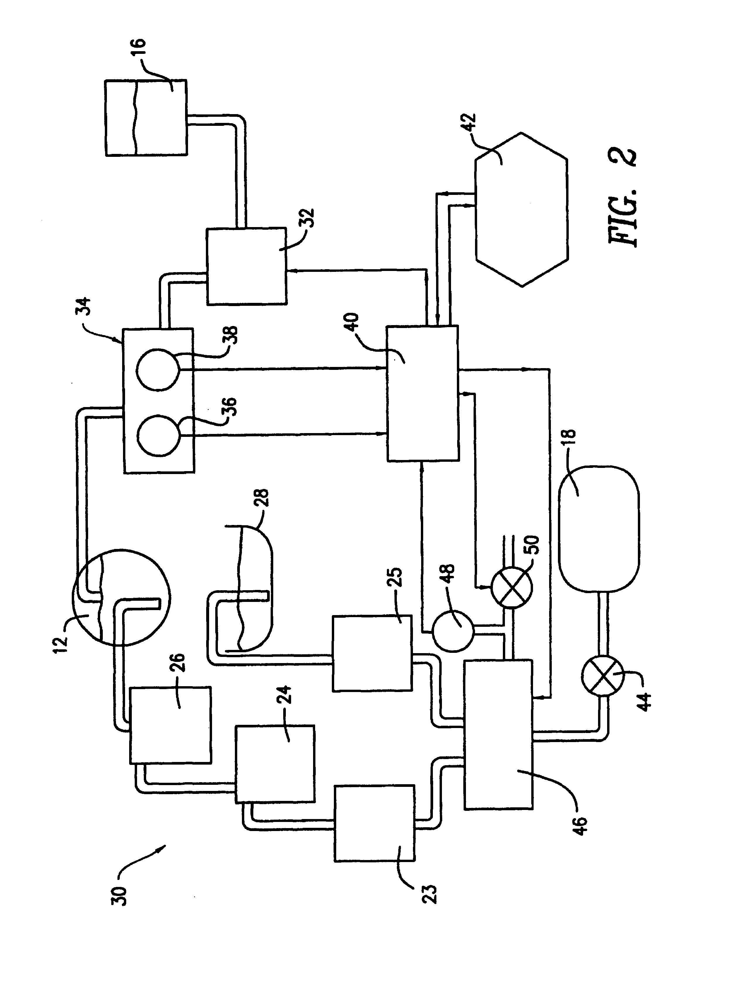
[0020]FIG. 1 shows a fluid management system 10′ in accordance with the prior art and includes those components necessary to simultaneously fill and drain a body cavity 12′, such as the uterus, with a liquid for distending the body cavity. The liquid may also be used for removing surgical debris, blood and exudate from the cavity 12′ during surgery via a continuous flow into and out of the cavity 12′. The fluid is pumped to the cavity 12′ by a pump 14′ which is fed by a suitable reservoir 16′ of sterile fluid, such as isotonic saline solution. Fluid pumped to the cavity 12′fills and distends it to facilitate performing a surgical procedure therein. A vacuum source 18′ provides suction under the control of a vacuum regulator 20′ to aid in withdrawing fluid from the cavity 12′. The regulator 20′ acts through a flow-back filter 22′ which prevents fluid withdrawn from the cavity 12′ from flowing into the vacuum regulator 20′ or the vacuum source 18′. The foregoing arrangement is used to...


PUM


Abstract

Apparatus for controlling the volume of surgical fluid present in a cavity in the body of a patient during surgery includes a conduit to the cavity for conducting the surgical fluid therefrom to at least one receptacle for receiving the fluid from said cavity. A source of vacuum assists in withdrawing fluid from the cavity and a vacuum controller interposed between the vacuum source and the receptacle controls the duration of time the receptacle is exposed to vacuum from the vacuum source. The apparatus preferably has a vacuum sensor for sensing vacuum levels in the receptacle when disconnected from the source of vacuum and shares the source of vacuum with another application, giving priority to maintaining a proper vacuum level in the receptacle.

Description

FIELD OF THE INVENTION[0001]The present invention relates to medical procedures and devices, more particularly to those devices used to infuse and remove fluids from the body of a patient during a surgical procedure.BACKGROUND OF THE INVENTION[0002]Endoscopic / laproscopic surgical procedures have grown significantly in popularity over the years due to the fact that they are minimally invasive and the miniature, remotely-controlled surgical instruments used have improved. To allow such procedures to be undertaken, means are frequently required to distend the patient's body cavity at the site of surgery to allow for surgical implement manipulation and visualization. Gasous or liquid insulflatants are used for this purpose depending upon the operation. Certain procedures also utilize a liquid insulflatant as a lavage for removing blood and excised tissue from the surgical site to maintain visibility and to clean the area. For example, in fibroid removal, the uterus is flooded with a cle...

Claims


Application Information

Patent Timeline
IPC IPC(8): A61M1/00A61M31/00A61M3/02
CPCA61M1/0031A61M1/0058A61M3/0258A61M1/0033A61M2205/123A61M2205/3355A61M2205/3379A61M2205/7536A61M2206/14Y10T137/86871Y10T137/2544A61M3/022A61M3/0216A61M3/0208A61M3/0212A61M1/742A61M1/74A61M1/77A61M3/0202A61M3/0201A61M1/72
Inventor CLARE, CHRISTOPHER R.GRIFFITHS, STEVE
Owner ETHICON INC
Why Eureka
Try Eureka