Vacuum closure device

a technology of vacuum closure and suction pump, which is applied in the direction of suction pump, dressing, physical therapy, etc., can solve the problems of not being aware of topical negative pressure devices capable of generating significant forces and unaffordable mechanical forces

Active Publication Date: 2011-03-03
SMITH & NEPHEW INC
View PDF43 Cites 82 Cited by
  • Summary
  • Abstract
  • Description
  • Claims
  • Application Information

AI Technical Summary

Benefits of technology

[0033]It is important that the covering element is sufficiently flexible to allow good conformability across the tissue but also sufficiently rigid to maintain a higher ratio of surfaces perpendicular to the tissue surface than those parallel to the tissue surface. This combination of flexibility and rigidity can be achieved most simply by combining relatively inflexible surfaces largely perpendicular to the tissue surface with flexible hinges.
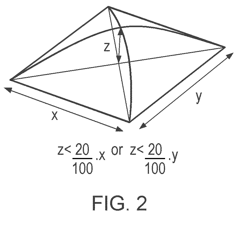
[0037]The shortest distance between the margins of the wound is defined as X, and the length of the bridging element is defined as Y. In embodiments of the invention Y is at least 110% of X. In further embodiments of the invention Y is at least 141% of X, as illustrated in FIG. 5. The tissue covering element can be defined in any single dimension as one with an internal surface length not exceeding 1000% of the shortest line between opposing points on the tissue margin (FIG. 5). The additional surface length is used to generate corrugations or folds that increase the surface area of the covering non-parallel to the tissue surface with the aim of maximising the perpendicularity of the covering to the tissue surface.
[0043]The tissue covering element must be attached to the patient in a manner that creates an substantially air tight seal of a quality that allows the vacuum source to maintain the target vacuum level within the enclosed volume. Practically, attachment to the patient can be achieved by means of any bonding mechanism. Preferably attachment is achieved by using an adhesive, such as an acrylate- or silicone-based adhesive commonly used for the attachment of medical devices and well known in the art. It is also possible that attachment can be achieved by utilising the pressure differential alone, in the same manner as a suction cup. However, this is difficult to achieve in reality due to the mechanical properties of tissue. Connection of the enclosed volume to the vacuum source can be achieved by any means obvious to a person skilled in the art, for example via a central penetrating port or in between the covering element and the bonded perimeter. Preferably, the vacuum source is connected to the enclosed volume by a port penetrating the surface of the covering element. It is additionally beneficial for the coupling of the vacuum source to the covering element to be achieved by a reversible means to facilitate repeated connection and disconnection over the duration of dressing wear. It is also preferable that connection and disconnection can be easily achieved by the patient and applier.

Problems solved by technology

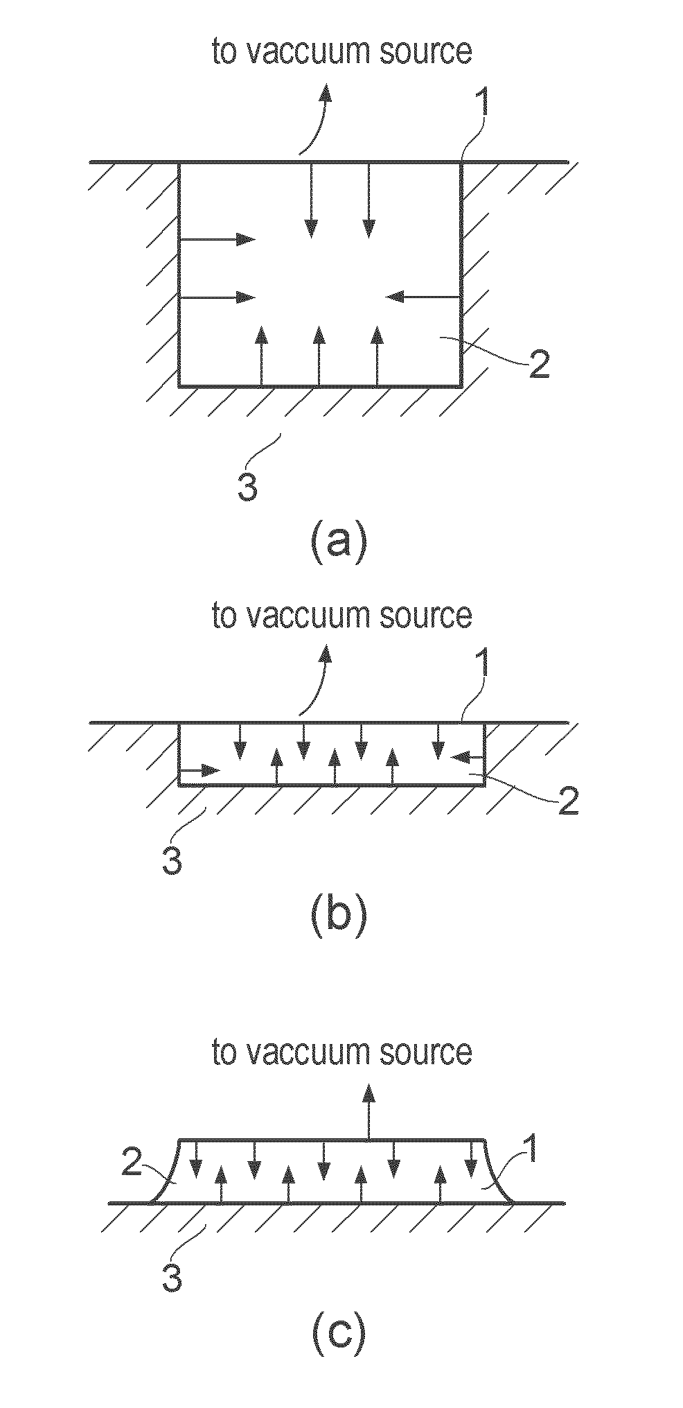
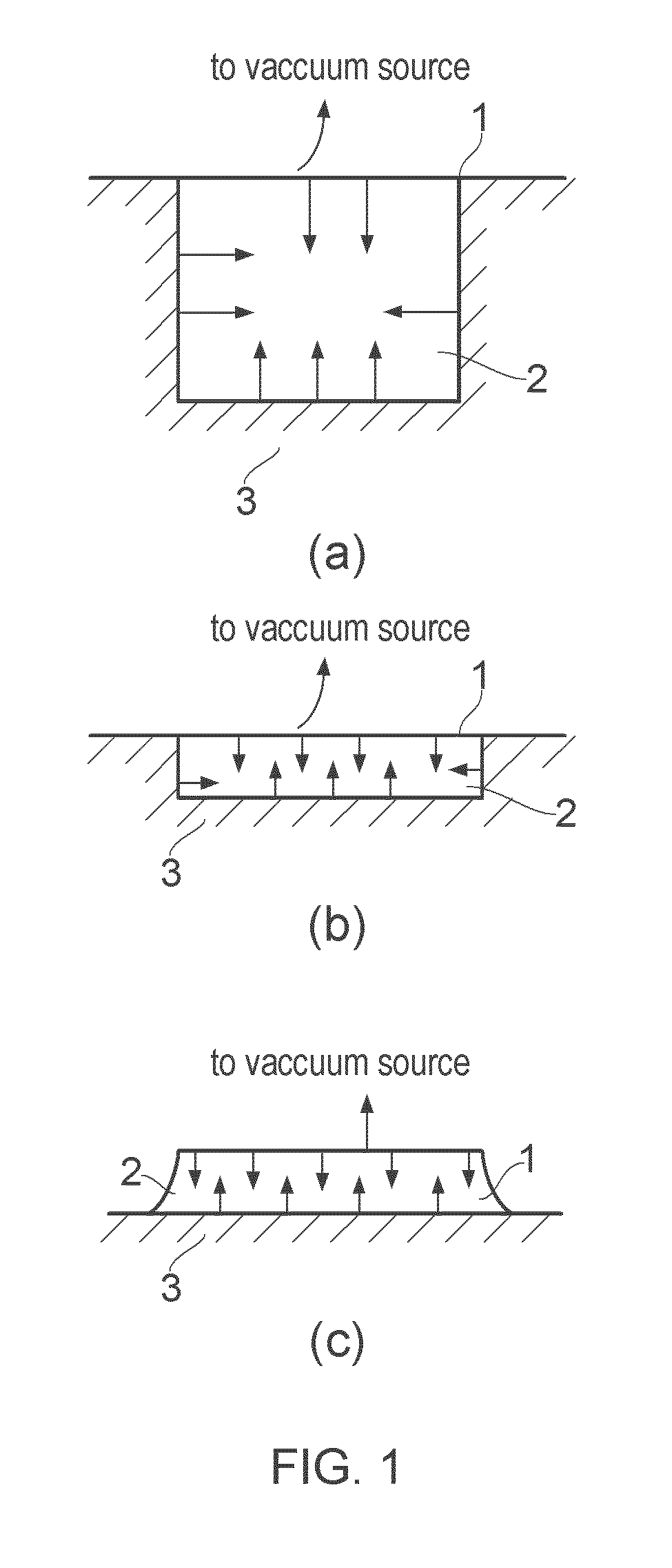
The problem here is that even if we assume uniform foam, drape and tissue mechanics across the patient population, the wound geometry will vary significantly from patient to patient. FIG. 1 demonstrates the effect of applying standard pressure and mechanics (tissue, drape and foam) to varying geometries of application; the force vectors generated vary widely.
However, for shallow wounds or incisional wounds, the desired mechanical forces are not afforded by the current method; in general, a compressive force perpendicular to the tissue surface is generated with a minor force generated in the direction parallel to the wound surface.
We are not aware of topical negative pressure devices capable of generating significant forces parallel to largely two-dimensional surfaces of attachment.

Method used


Image

  • Vacuum closure device
  • Vacuum closure device
  • Vacuum closure device

Examples


example 1

Construction of the Incision Closure Device Pictured in FIG. 3c

[0076]A device of the design pictured in FIG. 6 was moulded using a transparent, heat-curable medical grade silicone elastomer. The device had a dome-profiled pressure cracking valve (Minivalve International B. V.) cast into one of it's cavity faces. The flat surfaces of the inverted ‘V’ section of the device was reinforced with pre-cured mechanically stiff silicone elastomer.

example 2

Incision Closure with the Device of Example 1

[0077]The device prepared in Example 1 was positioned over a gaping linear incision made into a porcine belly cadaver. Partial vacuum was applied to the device via the crack-valve port. A pressure of −100 mmHg was achieved relative to ambient atmospheric pressure (660 mmHg absolute pressure). The device deformed by hinging about the highest point of the inverted ‘V’ section, causing contraction of the tissue around the incision in a direction perpendicular to it, thus achieving closure of the wound.

example 3

Construction of Device for the Closure of Open Area Wounds in Langer's Line Neutral Locations

[0078]A design of the concept pictured in FIG. 7 was moulded using a heat-curable medical grade silicone elastomer. The mould used was a collapsible funnel (Normann, Copenhagen) in the collapsed position. When the elastomer was cured, the concentric finned device was removed by opening the funnel.


PUM


Abstract

This invention relates to the design of tissue covering elements for use in vacuum assisted tissue apposition systems, wherein the geometry of the covering elements favours the application of contractile forces over compressive or extensive forces at the tissue interface.

Description

FIELD OF THE INVENTION[0001]This invention relates to the design of tissue covering elements for use in vacuum assisted tissue apposition systems, wherein the geometry of the covering elements favours the application of contractile forces over compressive or extensive forces at the tissue interface.BACKGROUND TO INVENTION[0002]Topical negative pressure (TNP) therapy has rapidly grown to be of excellent utility in the medical field, particularly in the treatment of wounds.[0003]A number of the current negative pressure systems available involve the application of a porous, deformable wound filler to the wound. The basic principle of TNP therapy is to create a closed cavity over the wound itself by means of a thin, flexible sealing film adhered to the patient's sound skin surrounding the wound; admitting one end of an aspirant conduit into the closed cavity, the conduit being sealed to the flexible film, for example; and connecting a distal end of the aspirant conduit to a vacuum sour...

Claims


Application Information

Patent Timeline
Patent Type & Authority Applications(United States)
IPC IPC(8): A61H7/00
CPCA61M1/0088A61M1/916A61M1/913A61M1/732A61F13/00068A61M27/00A61M1/67A61M1/80A61M1/962A61M1/71A61M1/60A61M1/604A61M1/78
Inventor GREENER, BRYAN
Owner SMITH & NEPHEW INC
Why Eureka
Try Eureka