
Vertebral disc prosthesis, notably for cervical vertebrae

a technology for cervical vertebrae and vertebrae, which is applied in the field of vertebral disc prosthesis notably for cervical vertebrae, can solve the problems of reduced dimensions, less or less rapid wear of articular surfaces, and inability to complete satisfaction of existing vertebral disc prosthesis, and achieves the effect of convenient engagemen

Active Publication Date: 2010-10-07
MEDICREA INT SA
View PDF6 Cites 11 Cited by
  • Summary
  • Abstract
  • Description
  • Claims
  • Application Information

AI Technical Summary

Benefits of technology

[0009]Its main goal is therefore to provide a vertebral disc prosthesis notably for cervical vertebrae, wherein wear of the articular surfaces remains reduced.
[0034]Said elastically deformable component may have deformability such that it may be engaged behind said head by simple circumferential stretching. This component may also not have such deformability, in which case the pin may not be firmly attached to said plate upon placement of the component and may be firmly attached to this plate once this placement is achieved.

Problems solved by technology

The existing vertebral disc prostheses, particularly those intended for cervical vertebrae, do not give complete satisfaction.
Indeed, the repeated movements which they undergo, result in more or less rapid wear of the articular surfaces, which in the case of cervical disc prostheses have reduced dimensions.
This wear leads to an undesirable diffusion of particles into the organism of the patient.
When the prosthesis comprises three components, there moreover exists a risk of expulsion of the intermediate component.
Further, the existing prostheses are relatively complex to make, taking into account stresses resulting from metal / metal or metal / polyethylene contacts.

Method used


Image

  • Vertebral disc prosthesis, notably for cervical vertebrae
  • Vertebral disc prosthesis, notably for cervical vertebrae
  • Vertebral disc prosthesis, notably for cervical vertebrae

Examples


Embodiment Construction

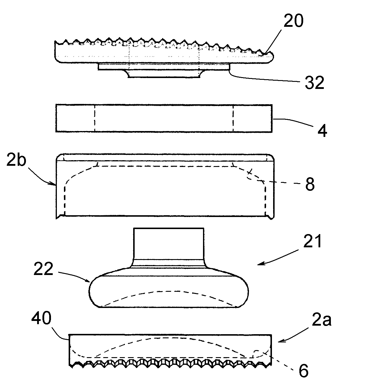
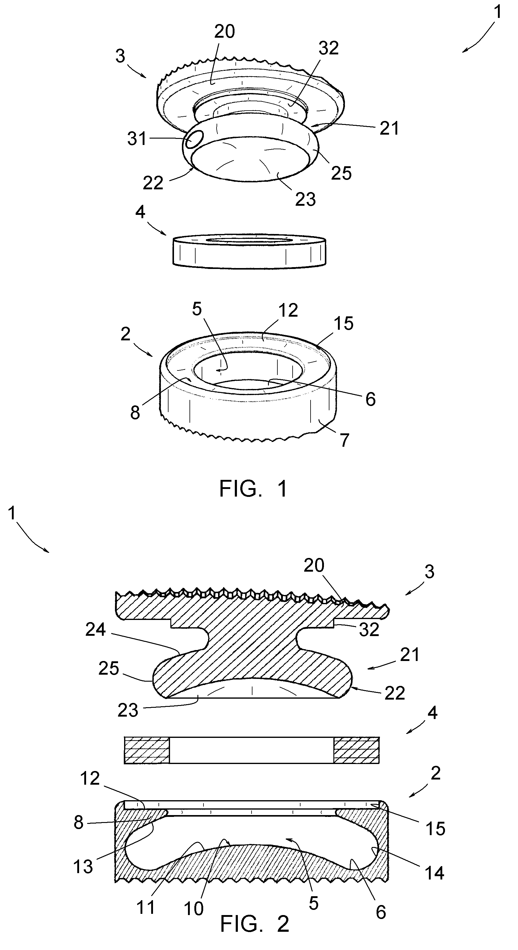
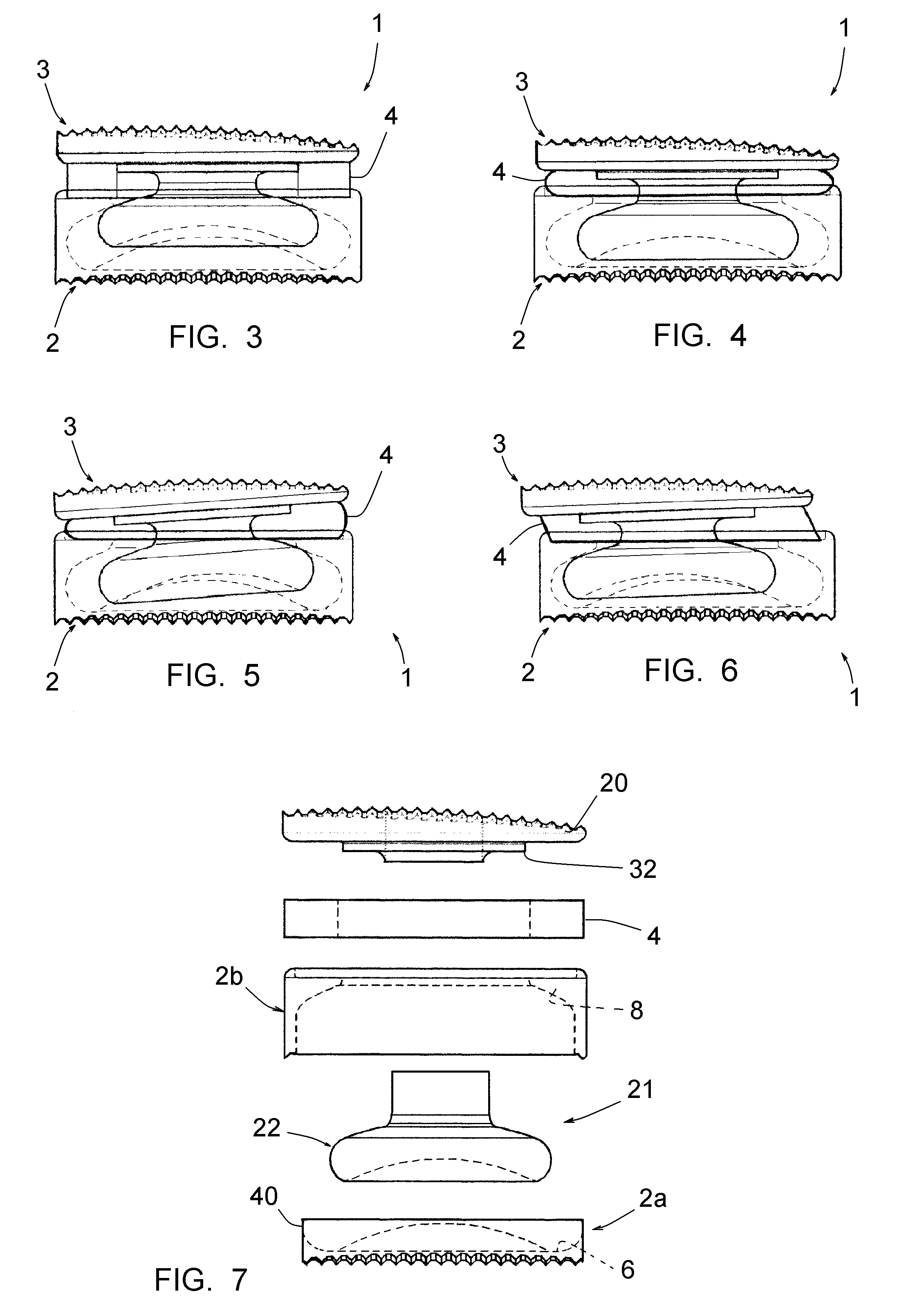
[0041]FIGS. 1-6 illustrate a vertebral disc prosthesis 1 notably for cervical vertebrae, comprising two components 2, 3 intended to be connected to the respective vertebral plates and a ring 4 in an elastically deformable material.

[0042]The component 2, which is the lower component in the illustrated example, delimits a housing, i.e. comprises a bottom 6, a peripheral wall 7 and at a distance from the bottom 6, an edge 8 extending radially inwards. The assembly is formed into a part of strong material, notably in ceramic or biocompatible metal.

[0043]The bottom 6 has a central convex boss 10 and with the shape of a spherical cap, forming a first articular surface 11.

[0044]The edge 8 forms, on the side opposite to the bottom 6, a peripheral supporting surface 12 and, on the side turned towards the bottom 6, a second articular surface 13. The first articular surface 11 is connected to the second articular surface 13 through a rounded peripheral area 14.

[0045]The component 2 further com...


PUM


Abstract

The present invention relates to a prosthesis including a first component that delimits a single central housing, including a bottom forming a first articular surface, a peripheral wall and, at a distance from the bottom, an edge extending inwards, a peripheral supporting surface, and on the side turned towards said bottom a second articular surface; and a second component including a plate intended to come into contact with the vertebral plate of the relevant vertebra and a single central pin with a widened head.

Description

[0001]This application is a national stage entry of PCT / IB2008 / 055048 filed Dec. 2, 2008, under the International Convention claiming priority over French Application No. 0708655 filed Dec. 12, 2007.FIELD OF THE INVENTION[0002]The present invention relates to a vertebral disc prosthesis notably for cervical vertebrae.BACKGROUND OF THE INVENTION[0003]Producing disc prostheses in two or three components with which the movements of the vertebrae may be reproduced is known. When the prosthesis comprises two components, these components comprise complementary articular surfaces, providing direct jointing of one component with the other. When the prosthesis comprises three components, both components anchored at the respective vertebrae are each jointed on an intermediate sliding component, generally in polyethylene.[0004]The existing vertebral disc prostheses, particularly those intended for cervical vertebrae, do not give complete satisfaction. Indeed, the repeated movements which they ...

Claims


Application Information

Patent Timeline
IPC IPC(8): A61F2/44
CPCA61F2/4425A61F2002/302A61F2002/30563A61F2002/30571A61F2002/30581A61F2310/00179A61F2002/30662A61F2002/30663A61F2002/443A61F2230/0065A61F2002/30649
Inventor SOURNAC, DENYSRYAN, DAVID
Owner MEDICREA INT SA
Learn More