Method for computing cooling redundancy at the rack level

a computing rack and cooling redundancy technology, applied in the field of data center management systems and methods, can solve problems such as excessive capital and operating costs

Active Publication Date: 2010-10-07
SCHNEIDER ELECTRIC IT CORP
View PDF99 Cites 47 Cited by
  • Summary
  • Abstract
  • Description
  • Claims
  • Application Information

AI Technical Summary

Problems solved by technology

To compensate for this rack-to-rack variation in (primary and failure-mode) cooling, a facility is often over designed—often by a large margin as the consequences of downtime are severe.
This over-provisioning of (primary and failure-mode) cooling equipment results in excessive capital and operating costs.

Method used


Image

  • Method for computing cooling redundancy at the rack level
  • Method for computing cooling redundancy at the rack level
  • Method for computing cooling redundancy at the rack level

Examples


Embodiment Construction

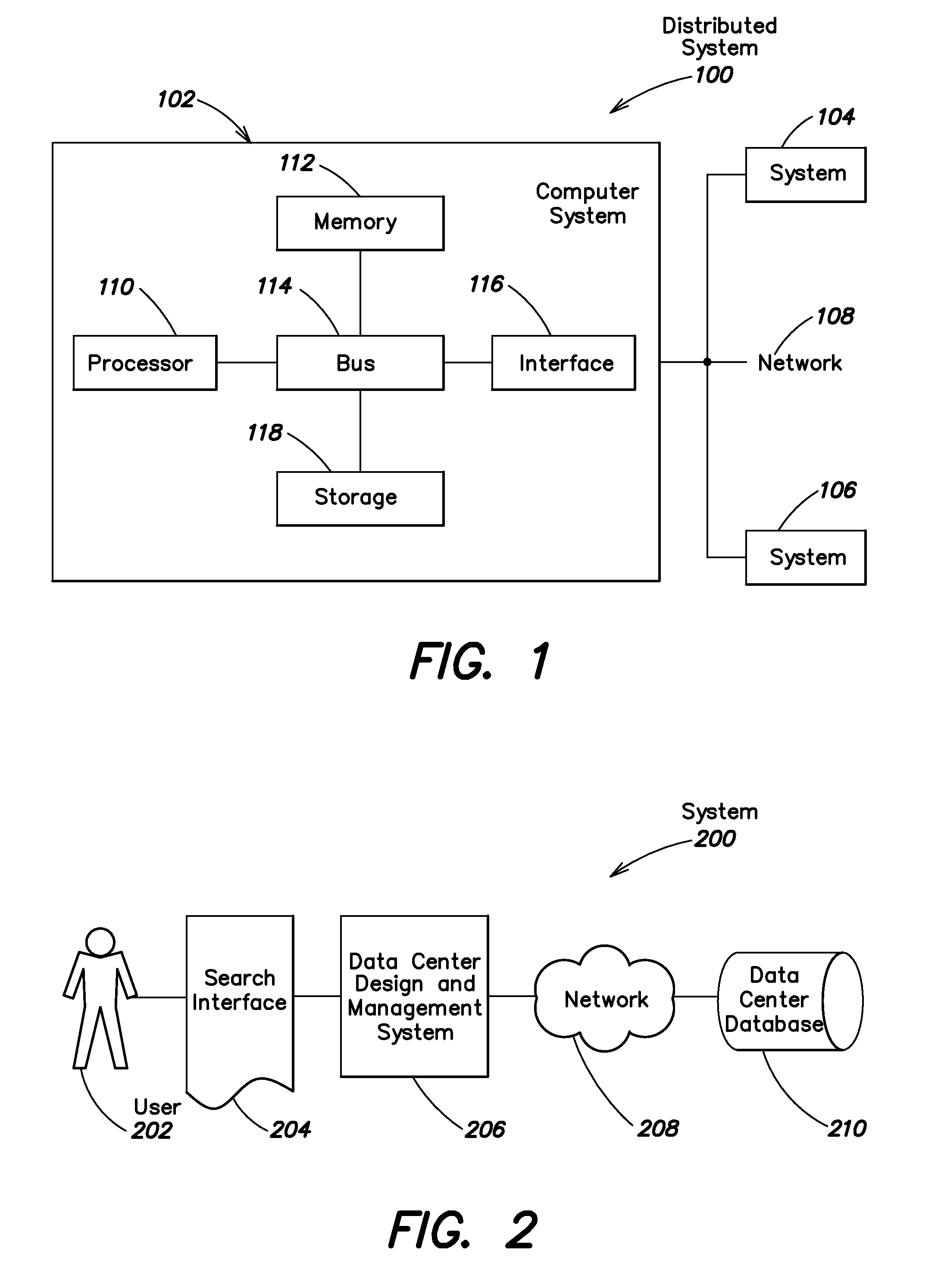
[0018]At least some embodiments in accord with the present invention relate to systems and processes through which a user may design data center configurations. These systems may facilitate this design activity by allowing the user to assess data center cooling redundancy at various levels of granularity, including cluster, row and rack levels.

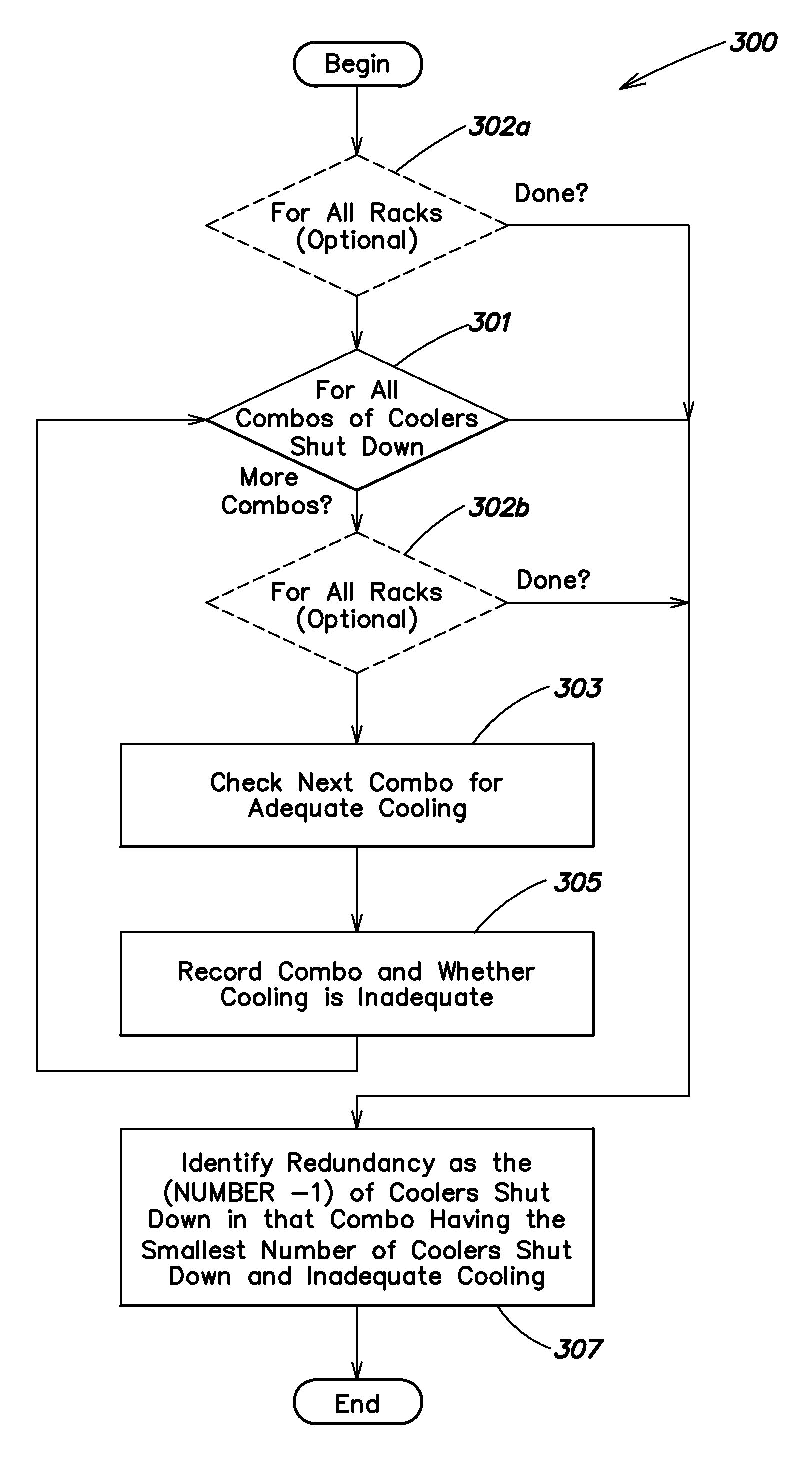
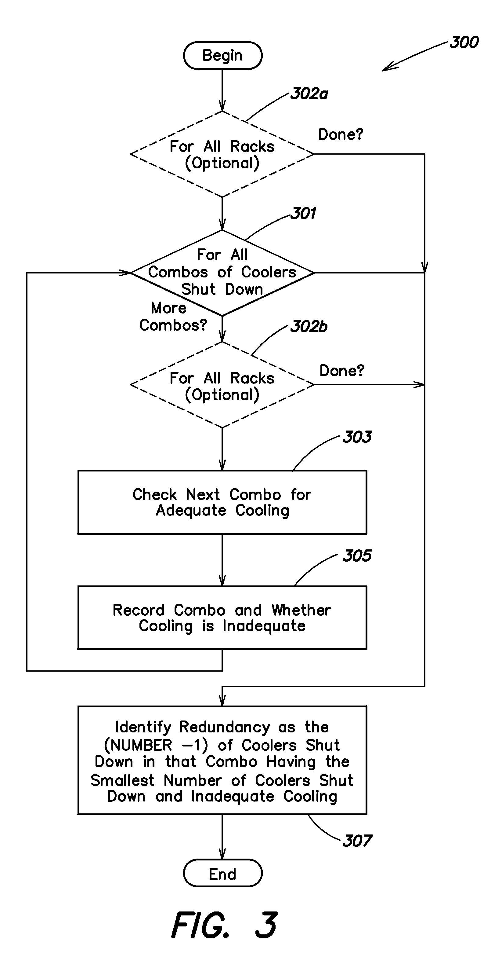
[0019]Design tools such as Computational Fluid Dynamics (CFD) and real-time cooling calculators incorporated in conventional tools offered by APC facilitate the proper matching of rack-by-rack IT load with primary cooling requirements; however, presently, there are no tools which, as described below, automate the process of determining the cooling available to each rack under various cooling failure scenarios. The data center designer or operator benefits from a design tool incorporating aspects of embodiments, and therefore which not only indicates the primary cooling performance at each rack location but also the redundancy at each rack loca...


PUM


Abstract

A system and method for designing aspects of a cooling system for a data center is provided. A method is provided including computing cooling redundancy at each rack position in a data center, in real time. The redundancy can be reported using the traditional N+1, N+2, etc. notation, where N is the number of coolers required to meet the primary cooling load type specification. The redundancy can also be reported in terms of a Cooling Reliability Index (CRI) which also takes into account the inherent availability of the specific cooling units in the design.

Description

BACKGROUND OF INVENTION[0001]1. Field of the Invention[0002]At least one embodiment in accord with the present invention relates generally to systems and methods for data center management, and more specifically, to systems and methods for managing data center cooling.[0003]2. Discussion of Related Art[0004]In response to the increasing demands of information-based economies, information technology networks continue to proliferate across the globe. One manifestation of this growth is the centralized network data center. A centralized network data center typically consists of various information technology equipment, collocated in a structure that provides network connectivity, electrical power and cooling capacity. Often the equipment is housed in specialized enclosures termed “racks” which integrate these connectivity, power and cooling elements. In some data center configurations, these racks are organized into rows and clusters having hot and cold aisles to decrease the cost asso...

Claims


Application Information

Patent Timeline
Patent Type & Authority Applications(United States)
IPC IPC(8): G06F17/10
CPCH05K7/20836G06F1/20
Inventor VANGILDER, JAMES W.HEALEY, CHRISTOPHER M.
Owner SCHNEIDER ELECTRIC IT CORP
Why Eureka
Try Eureka