Method for industrial energy and emissions investment optimization

a technology for energy and emissions, applied in the field of industrial energy and emissions investment optimization, can solve the problems of unresolved energy cost optimization and ghg emission compliance costs across multiple projects and locations, and the energy cost is expected to continue to increase in the future, so as to achieve the effect of maximizing the total net present value of savings

Inactive Publication Date: 2010-10-07
C3 INC
View PDF1 Cites 16 Cited by
  • Summary
  • Abstract
  • Description
  • Claims
  • Application Information

AI Technical Summary

Benefits of technology

[0014]The invention is an optimization method comprising of: (a) uniform and efficient model and associated methods for computing the energy and emission impacts of each of a range of technological and commercial options, and (b) an integrated and efficient optimization model for trading off the technological and commercial options against each other to arrive at a financially optimal solution that complies with regulatory caps on emission. The energy and emission impact model handles options such as energy efficiency measures, renewable energy projects, carbon capture projects and carbon offsets. In addition to handling the direct emissions, commonly referred to as Scope 1 emissions, the model handles indirect emissions resulting from purchased electricity or fuel, commonly referred to as Scope 2 emissions. The integrated optimization model selects the solution that maximizes the total net present value of savings across the various technological and commercial options considering the location specific rates, prices and carbon caps as well as the different levels of investments within each project to choose from; this model performs this optimization over a series of time periods respecting capital budget and operational budget constraints. The quantities of carbon offsets that must be purchased or sold are also determined as part of this integrated model.

Problems solved by technology

The energy costs are expected to continue to increase in the future.
The solution approaches that already exist deal with the energy requirements and GHG emission requirements separately and inadequately.
Even when they do work together, this is usually restricted to looking at a single process improvement opportunity at a time.
However, optimizing in an integrated manner energy costs and GHG Emission Compliance costs across multiple projects and locations has not been addressed.

Method used


Image

  • Method for industrial energy and emissions investment optimization
  • Method for industrial energy and emissions investment optimization
  • Method for industrial energy and emissions investment optimization

Examples


Embodiment Construction

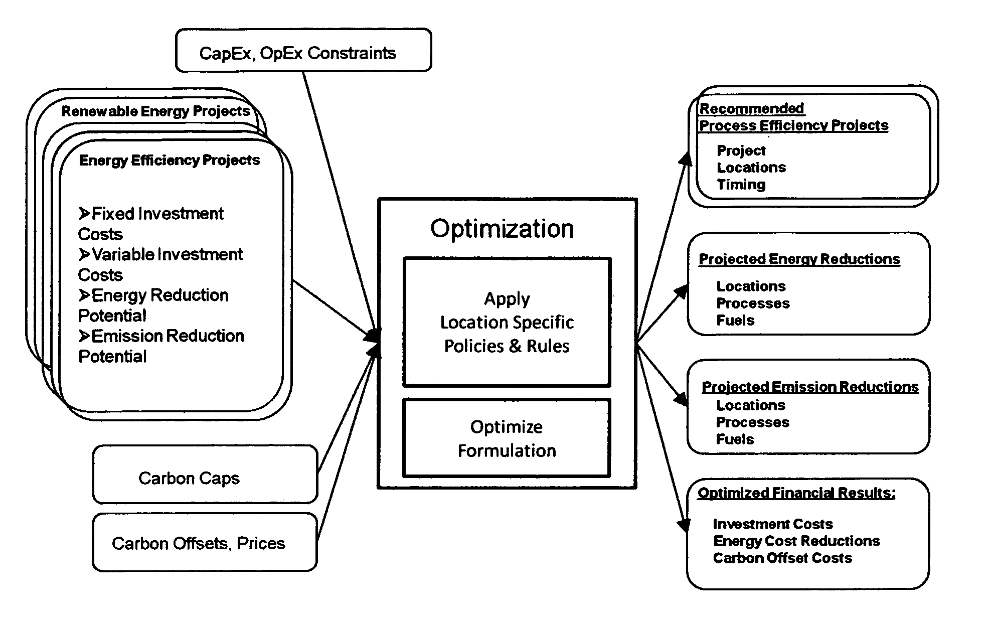
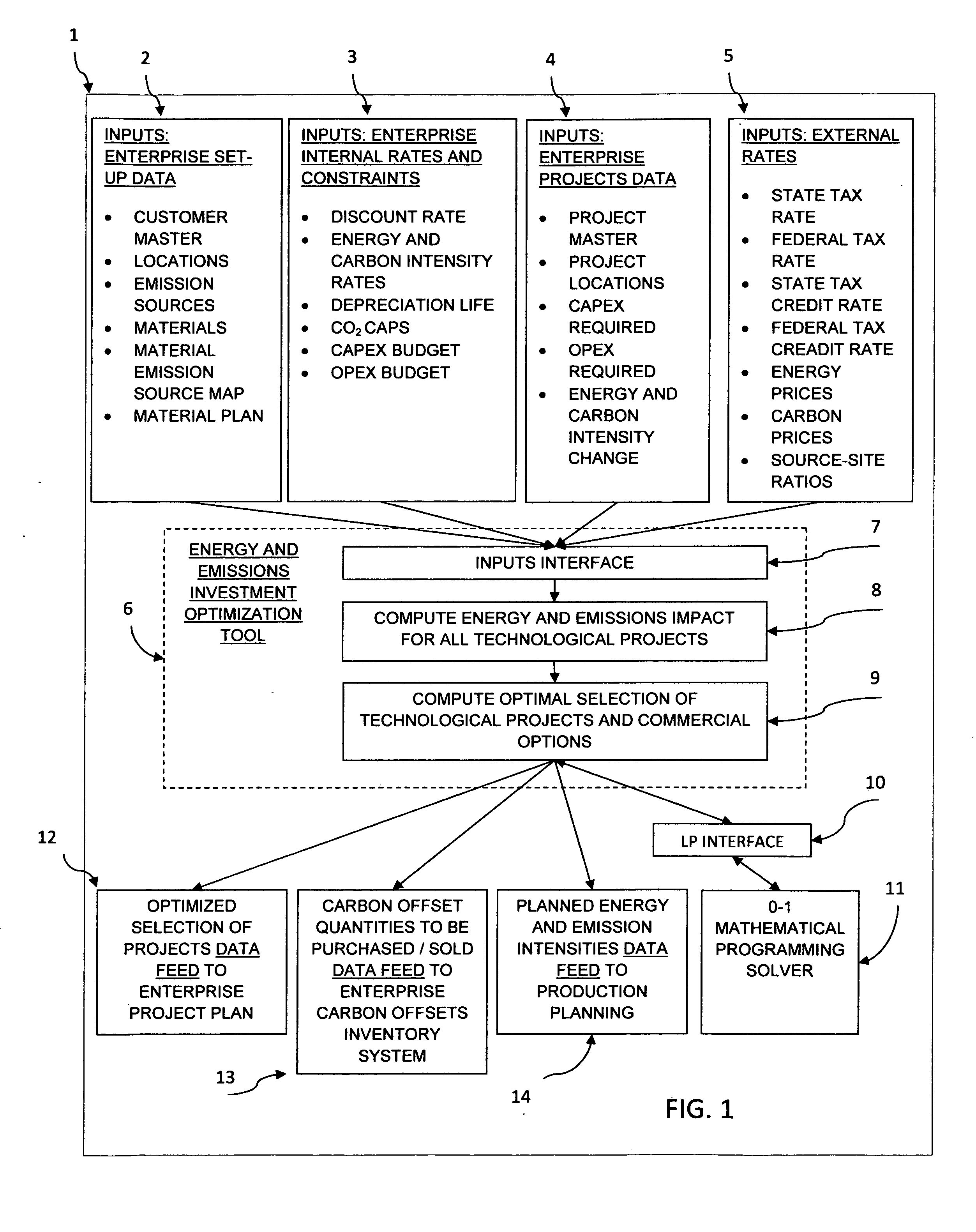
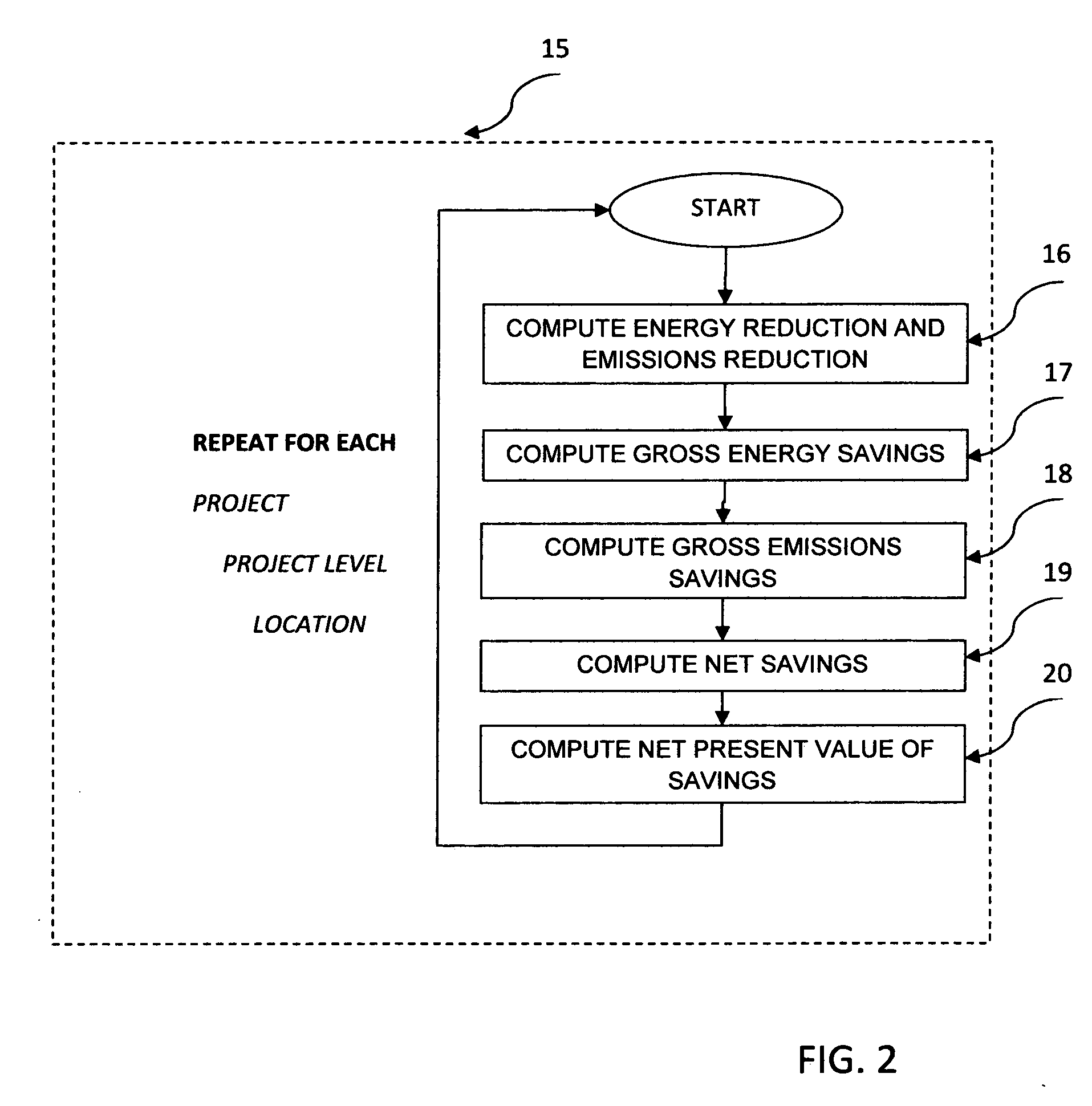
[0024]The invention is the method (box 6) of selecting an optimal mix of energy efficiency and emission abatement projects, which is comprised of two major stages: I. computing the impact of each energy efficiency and emission abatement project; II. selecting an optimal mix of projects that considers business objectives and business factors and satisfy business constraints. Referring to FIG. 1, boxes 2-5 represent the inputs to this method, which are communicated to the method through inputs interface (box 7). The two stages in the method are represented by boxes 8 and 9 respectively. Box 10 represents a standard interface to a commercial solver; box 11 represents a commercial mathematical program solver; box 12 represents an enterprise storage for storing Energy and Emissions Project Plans; box 13 represents an enterprise storage for Carbon Offsets Inventory. Before continuing, the following are terminology definitions which will be sued herein.

TERMINOLOGY

Inputs: Enterprise Set-up ...


PUM


Abstract

The invention is an optimization method comprising of: (a) uniform and efficient model and associated methods for computing the energy and emission impacts of each of a range of technological and commercial options, and (b) an integrated and efficient optimization model for trading off the technological and commercial options against each other to arrive at a financially optimal solution that complies with regulatory caps on emission. The energy and emission impact model handles options such as energy efficiency measures, renewable energy projects, carbon capture projects and carbon offsets. In addition to handling the direct emissions, the model handles indirect emissions resulting from purchased electricity or fuel. The integrated optimization model selects the solution that maximizes the total net present value of savings across the various technological and commercial options considering the location specific rates, prices and carbon caps as well as the different levels of investments within each project to choose from; this model performs this optimization over a series of time periods respecting capital budget and operational budget constraints. The quantities of carbon offsets that must be purchased or sold are also determined as part of this integrated model.

Description

BACKGROUND OF THE INVENTION[0001]This invention is in the field of helping businesses strike a balance between corporate energy and emission reduction costs and the costs of environmental compliance. The energy costs are expected to continue to increase in the future. According to the estimates from the U.S. Environmental Protection Agency, aggregated energy consumption across many of the manufacturing sectors is projected to increase by 20 percent from 2004 levels by 2020, and CO2e emissions (i.e. CO2 equivalent emissions for all the six green house emission gases) are projected to increase by 14 percent (“Energy Trends in Selected Manufacturing Sectors: Opportunities and Challenges for Environmentally Preferable Energy Outcomes”, U.S. Environmental Protection Agency, March 2007). The volumes of green house gas emissions are expected to continue to rise in the future. In California, for example, the emission levels are projected to grow from a 2004 level of 500 MMT CO2e to 600 MMT ...

Claims


Application Information

Patent Timeline
Patent Type & Authority Applications(United States)
IPC IPC(8): G06Q10/00G06Q99/00G06Q40/00
CPCG06Q10/06G06Q10/067Y04S10/58G06Q40/10G06Q40/06Y04S10/50Y02P80/10Y02P90/82Y02P90/84Y02P90/845Y02P90/90
Inventor SRINIVASAN, RAMESH
Owner C3 INC
Why Eureka
Try Eureka