
Tile tray

Active Publication Date: 2010-10-14
GORDON ANDERSON
View PDF18 Cites 48 Cited by
  • Summary
  • Abstract
  • Description
  • Claims
  • Application Information

AI Technical Summary

Benefits of technology

[0020]In one embodiment, the tile tray includes an adhesive means for securing the tile to the base. Preferably, the adhesive means includes one or more adhesive pads disposed on the base, the adhesive pads including a protective liner. More preferably, the adhesive means includes liquid glue, bonding composition, liquid cement, or other type of liquid adhesive. Depending on the type of adhesive means used, the tiles may be releasable from the base. Advantageously, this allows the tiles to be replaced in case of breakage or merely a change of design.
[0025]In one embodiment, the base includes a plurality of adhesion apertures, the adhesion apertures being adapted to provide a flow path for a liquid adhesive thereby to better adhere the tile to the tile tray upon setting of the liquid adhesive. Preferably, each aperture includes a rebate peripherally extending around its underside thereby to further assist in adhering the tile to the tile tray upon setting of the liquid adhesive.
[0026]In one embodiment, the base includes a textured pattern on its upper surface for assisting in adhering the tile to the tile tray.
[0035]While it is easier to manipulate the tile trays and connect them together when they are empty, it will be appreciated that the step of inserting the tiles into the tile trays may be performed prior to the tile trays being connected together.
[0036]In one embodiment, the method further includes the step of applying a grout to the gaps between the tile tiles. Alternatively, a settable rubber based and water resistant clear sealant is applied to the gap region between the tile trays and a moulded ‘grout-resembling’ resilient plastic profile is placed over the sealant. In this way, the connecting regions of contiguous modular panels are covered to advantageously give the appearance of a traditionally laid grouted tiled surface.

Problems solved by technology

While spacing aids are available, they provide additional cost as well as being relatively difficult to use effectively.
In addition, traditional tile laying cement can be messy to use, often drying to form visual imperfections on the surface of the tiles.
For these reasons, both wall and floor tiling is typically not ideally suited to the do-it-yourself home handyman or renovator.
The system taught by WO 2005 / 124053, however, is subject to several problems and limitations.
Firstly, the panels are heavy and difficult to manipulate during installation.
Consequently, the user has a relatively limited selection when compared to the tiles available on the market.

Method used


Image

  • Tile tray
  • Tile tray
  • Tile tray

Examples


Embodiment Construction

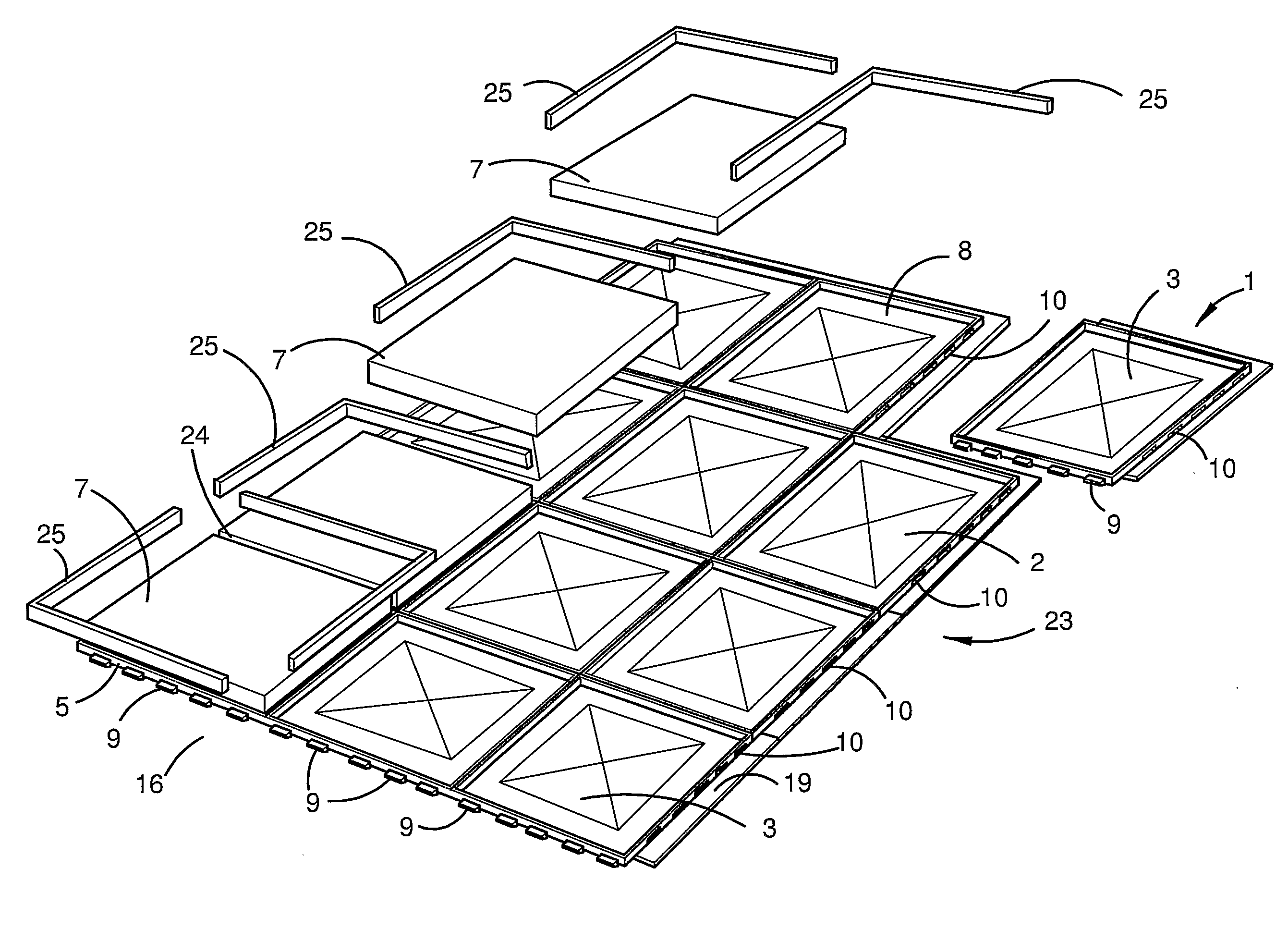
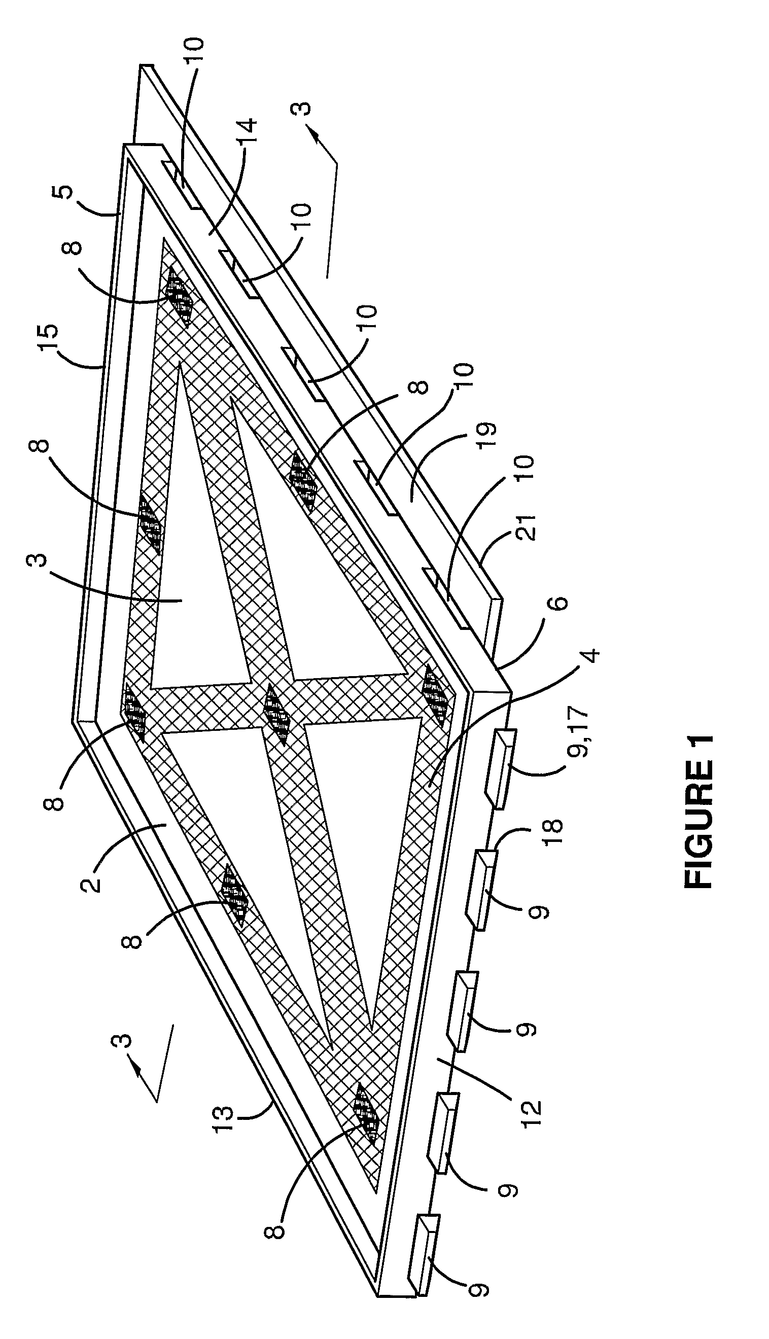
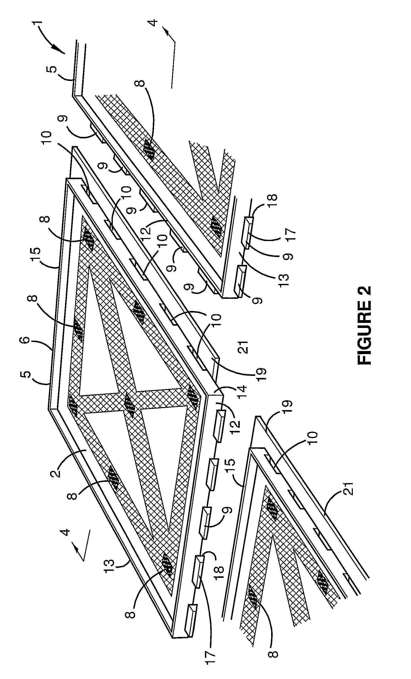
[0052]Referring to the accompanying drawings and initially to FIGS. 1 to 4, there is depicted a tile tray 1 for housing a tile 7 in accordance with the present invention. It is envisaged that a plurality of tile trays be used to house a plurality floor or wall tiles, thereby to define a modular floor or wall system.

[0053]The tile tray 1 includes a substantially planar base 2 having a support surface 3 with a textured pattern or surface 4 disposed thereon. In the illustrated embodiment, the textured pattern extends around the periphery of the support surface and in a X-shape across the surface. It will be appreciated, however, that the textured surface may be have other configurations. Moreover, in alternate forms the support surface may additionally include a plurality of adhesion apertures.

[0054]The tile tray 1 further includes a continuous locating edge 5 substantially extending from the periphery 6 of the base to define a region, which is generally dimensionally identical to and ...


PUM

PropertyMeasurementUnit
Densityaaaaaaaaaa

Abstract

A tile tray (1) including a generally planar base (2) and two or more retaining members (5) adapted to locate and retain a tile (7) to the base. The tile tray (1) further includes a coupling means for connecting two or more of the tile trays in a substantially aligned configuration.

Description

FIELD OF THE INVENTION[0001]The present invention relates generally to modular floor and wall covering systems and, in particular, to tiled wall and floor covering systems.[0002]The invention has been developed primarily as a tile tray for use with tiles and pavers and will be described hereinafter with reference to this application. However, it will be appreciated that the invention is not limited to this particular field of use.BACKGROUND OF THE INVENTION[0003]The following discussion of the prior art is intended to place the invention in an appropriate technical context and enable the associated advantages to be fully understood. However, any discussion of the prior art throughout the specification should not be considered as an admission that such art is widely known or forms part of the common general knowledge in the field.[0004]Traditional tile laying techniques require a reasonably high level of skill to prepare the surface prior to tiling and to align and consistently space...

Claims


Application Information

Patent Timeline
IPC IPC(8): E04F15/16
CPCE01C5/001E04F15/02E04F13/142E04F15/02194E04F15/087E04F15/105E04F15/107
Inventor ANDERSON, GORDON
Owner GORDON ANDERSON
Features
  • Generate Ideas
  • Intellectual Property
  • Life Sciences
  • Materials
  • Tech Scout
  • Unparalleled Data Quality
  • Higher Quality Content
  • 60% Fewer Hallucinations
Learn More