Fin, heat exchanger and heat exchanger assembly

a technology of heat exchanger and fin, which is applied in the direction of heat exchange apparatus, lighting and heating apparatus, tubular elements, etc., can solve the problems of irregular deformation of/or the connection point, difficult control of the arranging density of the fin b>1/b>′ in the heat exchanger, and difficulty in pressing the circular arc root segment, etc., to achieve easy control, easy deformation, and high heat transfer coefficien

Active Publication Date: 2010-10-14
SANHUA HANGZHOU MICRO CHANNEL HEAT EXCHANGER +1
View PDF10 Cites 10 Cited by
  • Summary
  • Abstract
  • Description
  • Claims
  • Application Information

AI Technical Summary

Benefits of technology

[0011]Since the radius R of the substantially-circular arc segment is larger than the radius r of the substantially-circular arc transition segment, after being assembled and welded to the heat exchanger, the substantially-circular arc segment is relatively easy to deform, and the shapes of the straight segment and substantially-circular arc transition segment are substantially unchanged. Therefore, the deformation of the fin is regular and easy to control. The arranging density of the fin in the heat exchanger is

Problems solved by technology

Since the circular arc shaped root segment and the straight segment are directly connected to each other, the circular arc shaped root segment is difficult to be pressed.
Therefore, the deformation of the circular arc shaped root segment and/or the connection point is irregular and difficult to control, and the fins 1′ are different from each other in deforma

Method used


Image

  • Fin, heat exchanger and heat exchanger assembly
  • Fin, heat exchanger and heat exchanger assembly
  • Fin, heat exchanger and heat exchanger assembly

Examples


Embodiment Construction

[0030]Reference will be made in detail to embodiments of the present invention. The embodiments described herein with reference to drawings are explanatory, illustrative, and used to generally understand the present invention. The embodiments shall not be construed to limit the present invention. The same or similar elements and the elements having same or similar functions are denoted by like reference numerals throughout the descriptions.

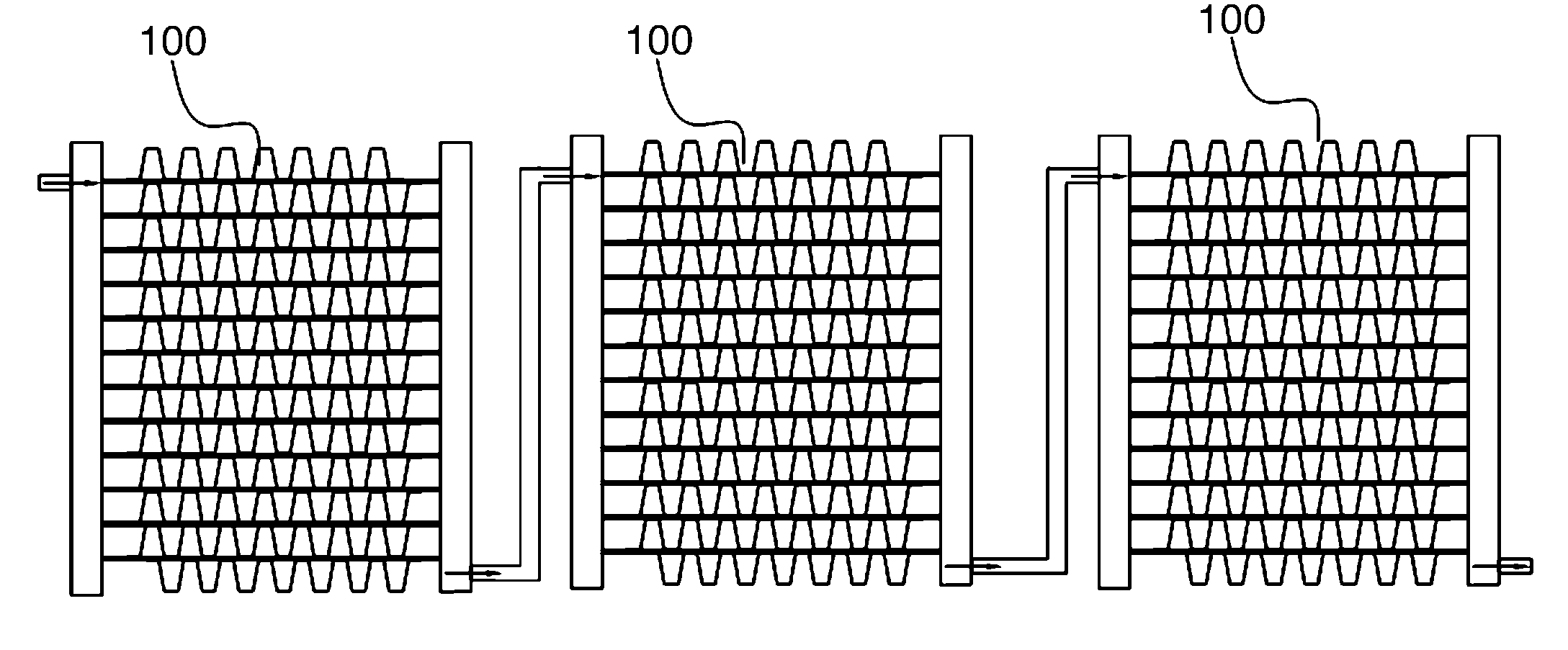
[0031]The fin 1 according to an embodiment of the present invention will be described in detail below with reference to FIGS. 1-5, in which the heat exchanger is a micro-channel heat exchanger. However, a person skilled in the art will understand that the heat exchanger employing the fin is not limited to a micro-channel heat exchanger.

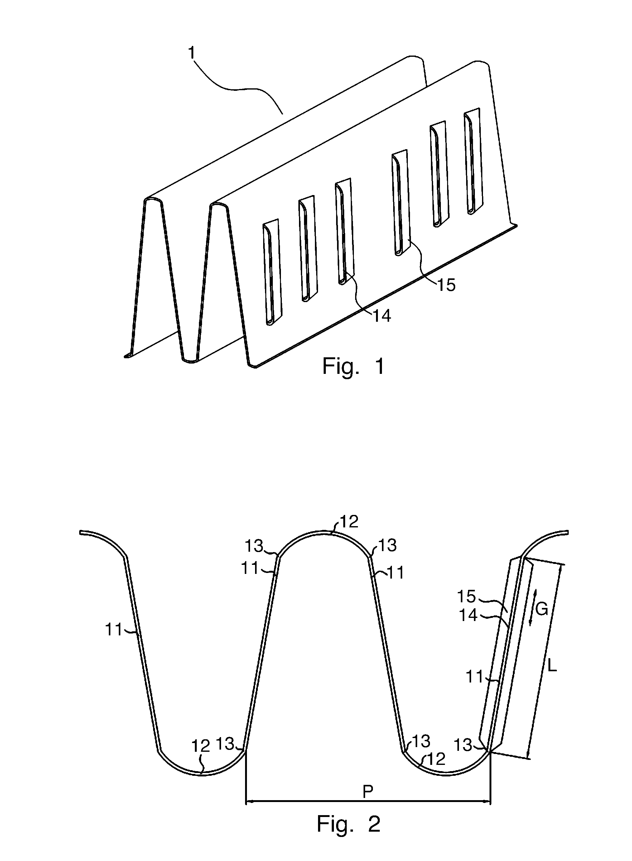
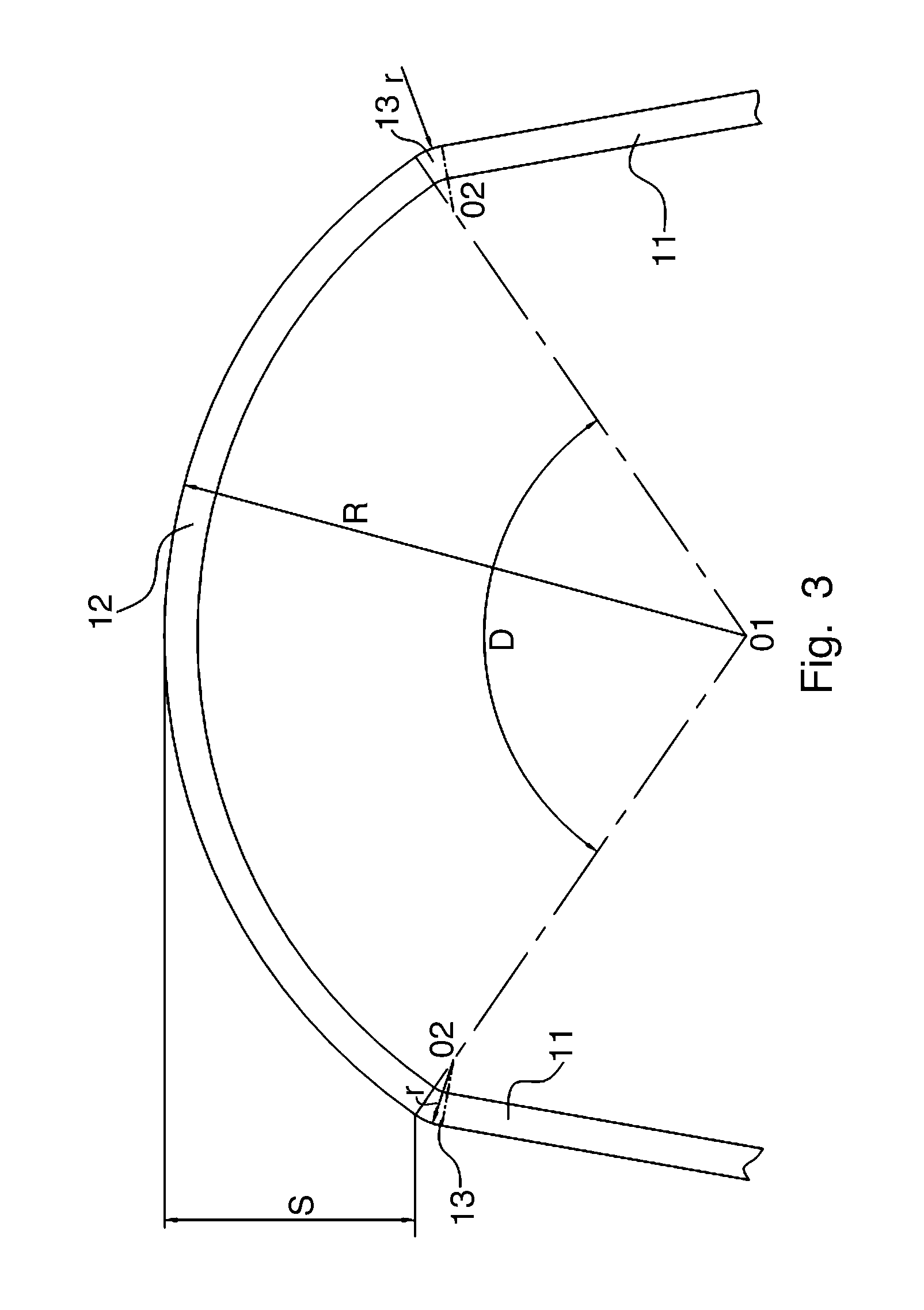
[0032]FIG. 1 is a perspective view of a part of the fin 1 before the fin 1 is assembled and welded to the micro-channel heat exchanger. FIG. 2 is a side view of the part of the fin 1 shown in FIG. 1, and FIG. 3 is a...


PUM


Abstract

The present invention discloses a fin of heat exchanger comprising a straight segment; a substantially-circular arc segment having a radius of R; and a substantially-circular arc transition segment connected between the straight segment and the substantially-circular arc segment and having a radius of r, wherein R>r. According to the present invention, after being assembled and welded to the heat exchanger, the substantially-circular arc segment is relatively easy to deform, and the shapes of the straight segment and substantially-circular arc transition segment are substantially unchanged. Therefore, the deformation of the fin is regular and easy to control. The arranging density of the fin in the heat exchanger is uniform, and the shape of the fin can meet the design requirements. In addition, the shape stability and the heat transfer coefficient of the fin are high.

Description

CROSS REFERENCE TO RELATED APPLICATIONS[0001]This application is entitled to the benefit of and incorporates by reference essential subject matter disclosed in Chinese Patent Application No. 200910133642.8 filed on Apr. 13, 2009.BACKGROUND OF THE INVENTION[0002]1. Field of the Invention[0003]The present invention generally relates to a fin, a heat exchanger having the fin, and a heat exchanger assembly, and more particularly, to a corrugated fin having a substantially sinusoidal shape, a micro-channel heat exchanger and a heat exchanger assembly comprising a plurality of micro-channel heat exchangers.[0004]2. Description of the Related Art[0005]Conventional corrugated fins having a substantially sinusoidal shape are widely used in heat exchangers. Conventional corrugated fins generally comprise a straight segment and a circular arc shaped root segment which are connected with each other. During manufacturing of the heat exchanger, as shown in FIGS. 10 and 11, the fin 1′ is disposed ...

Claims


Application Information

Patent Timeline
IPC IPC(8): F28F9/02
CPCF28F1/128F28F1/126
Inventor YUAN, GAOHUANG, LIN-JIE
Owner SANHUA HANGZHOU MICRO CHANNEL HEAT EXCHANGER
Why Eureka
Try Eureka