Preselector amplifier

a technology of amplifier and amplifier, applied in the direction of pulse technique, oscillation generator, antenna, etc., can solve the problem of large size of conventional passive filters

Active Publication Date: 2010-10-14
VIASAT INC
View PDF55 Cites 18 Cited by
  • Summary
  • Abstract
  • Description
  • Claims
  • Application Information

AI Technical Summary

Problems solved by technology

The conventional passive filte

Method used


Image

  • Preselector amplifier
  • Preselector amplifier
  • Preselector amplifier

Examples


Embodiment Construction

[0022]While exemplary embodiments are described herein in sufficient detail to enable those skilled in the art to practice the invention, it should be understood that other embodiments may be realized and that logical material, electrical, and mechanical changes may be made without departing from the spirit and scope of the invention. Thus, the following detailed description is presented for purposes of illustration only.

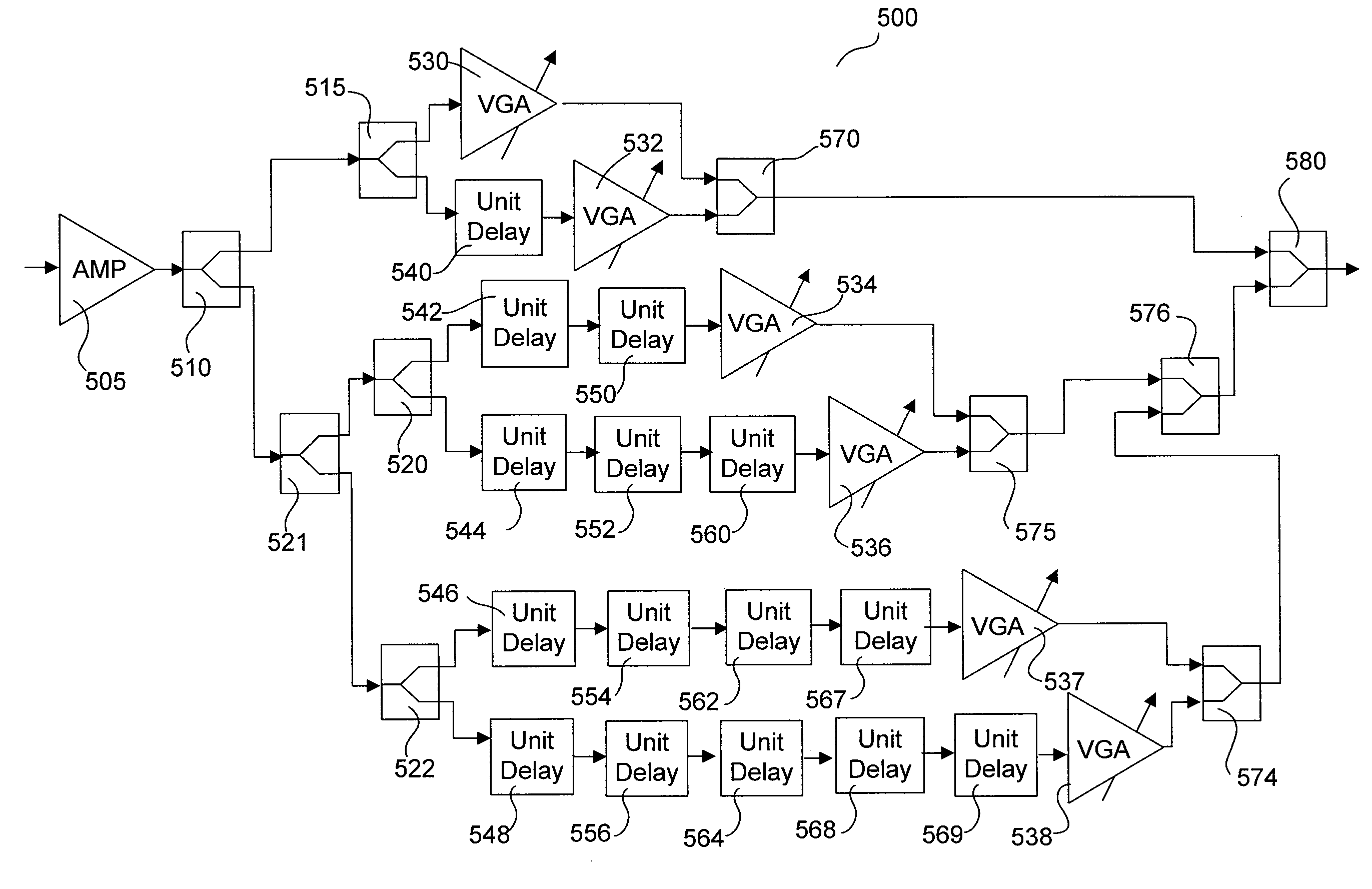
[0023]In an exemplary embodiment, a preselector amplifier is comprised of various components. The various components may include a vector generator, an active power splitter, an active power combiner, or the like. The preselector amplifier may be integral to and / or coupled to a communications system. The communications system may be at least one of a transceiver, receiver and / or transmitter. The communications system may transmit radio frequency (RF) signals.

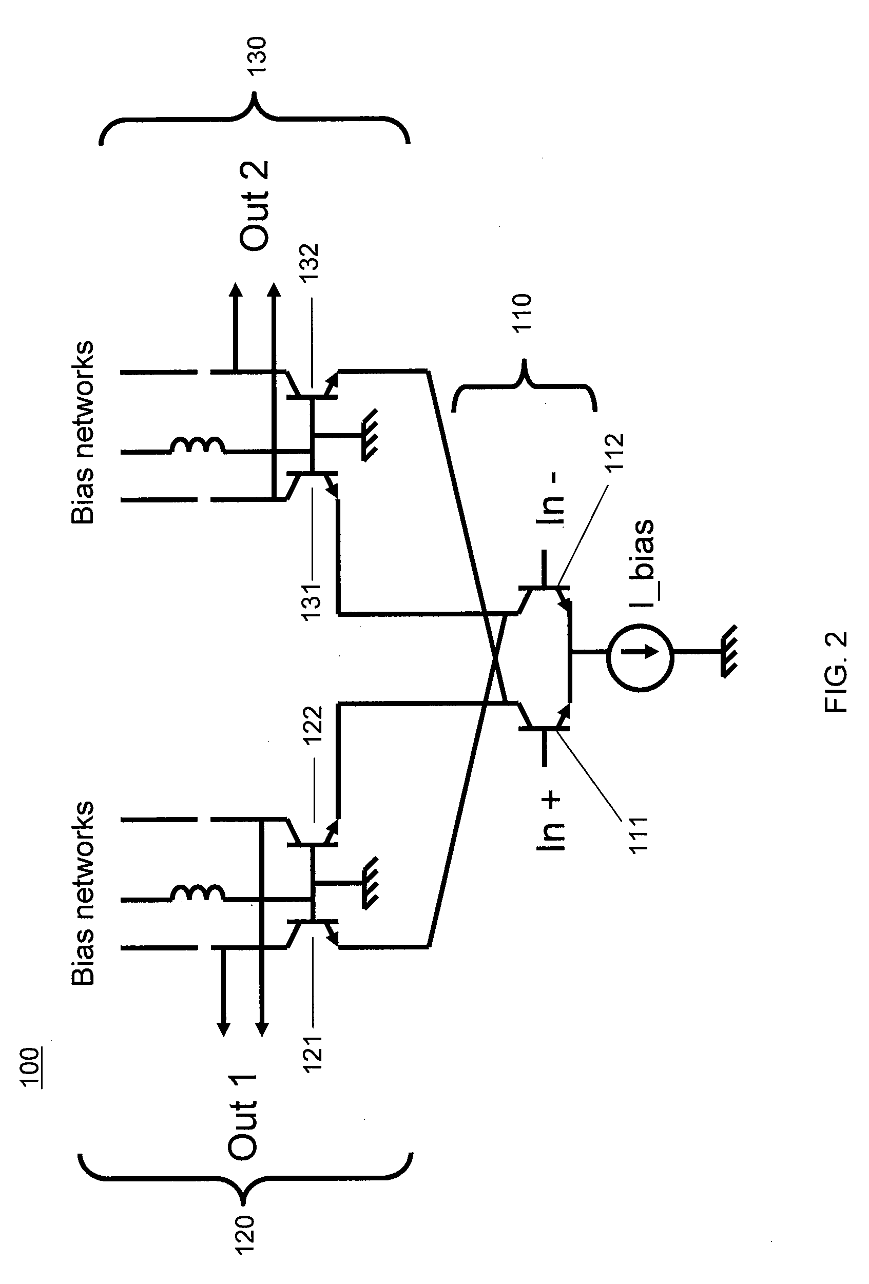
[0024]Active Splitter: FIG. 2 illustrates a schematic of an exemplary active power splitter. In an exemplary ...


PUM


Abstract

A preselector amplifier system and method including of various components is described. The various components may include a vector generator, an active power splitter, an active power combiner, or the like. The preselector amplifier may be integral to and/or coupled to a communications system. The communications system may be at least one of a transceiver, receiver and/or transmitter. The communications system may transmit radio frequency (RF) signals.

Description

CROSS REFERENCE TO RELATED APPLICATIONS[0001]This application is a non-provisional of U.S. Provisional Application No. 61 / 237,967, entitled “ACTIVE BUTLER AND BLASS MATRICES,” which was filed on Aug. 28, 2009. This application is also a non-provisional of U.S. Provisional Application No. 61 / 259,375, entitled “ACTIVE HYBRIDS FOR ANTENNA SYSTEMS,” which was filed on Nov. 9, 2009. This application is a non-provisional of U.S. Provisional Application No. 61 / 234,513, entitled “ACTIVE FEED FORWARD AMPLIFIER,” which was filed on Aug. 17, 2009. This application is a non-provisional of U.S. Provisional Application No. 61 / 222,354, entitled “ACTIVE PHASED ARRAY ARCHITECTURE,” which was filed on Jul. 1, 2009. This application is a non-provisional of U.S. Provisional Application No. 61 / 168,913, entitled “ACTIVE COMPONENT PHASED ARRAY ANTENNA,” which was filed on Apr. 13, 2009. This application is also a non-provisional of U.S. Provisional Application No. 61 / 259,049, entitled “DYNAMIC REAL-TIME P...

Claims


Application Information

Patent Timeline
IPC IPC(8): H03F3/68H04B1/00
CPCH01Q3/26H01Q3/36H01Q3/34G06G7/12H01Q15/242H03H11/36
Inventor SAUNDERS, DAVID R.
Owner VIASAT INC
Why Eureka
Try Eureka