Heat sink

a technology of heat sink and heat sink, which is applied in the direction of instruments, electrical apparatus casings/cabinets/drawers, and semiconductor/solid-state device details, etc., can solve the problem of waste of material from cutting fins

Inactive Publication Date: 2010-10-14
HON HAI PRECISION IND CO LTD
View PDF16 Cites 3 Cited by
  • Summary
  • Abstract
  • Description
  • Claims
  • Application Information

AI Technical Summary

Problems solved by technology

However, cutting the fins wastes material, which is uneconomical.

Method used


Image

  • Heat sink
  • Heat sink
  • Heat sink

Examples


Embodiment Construction

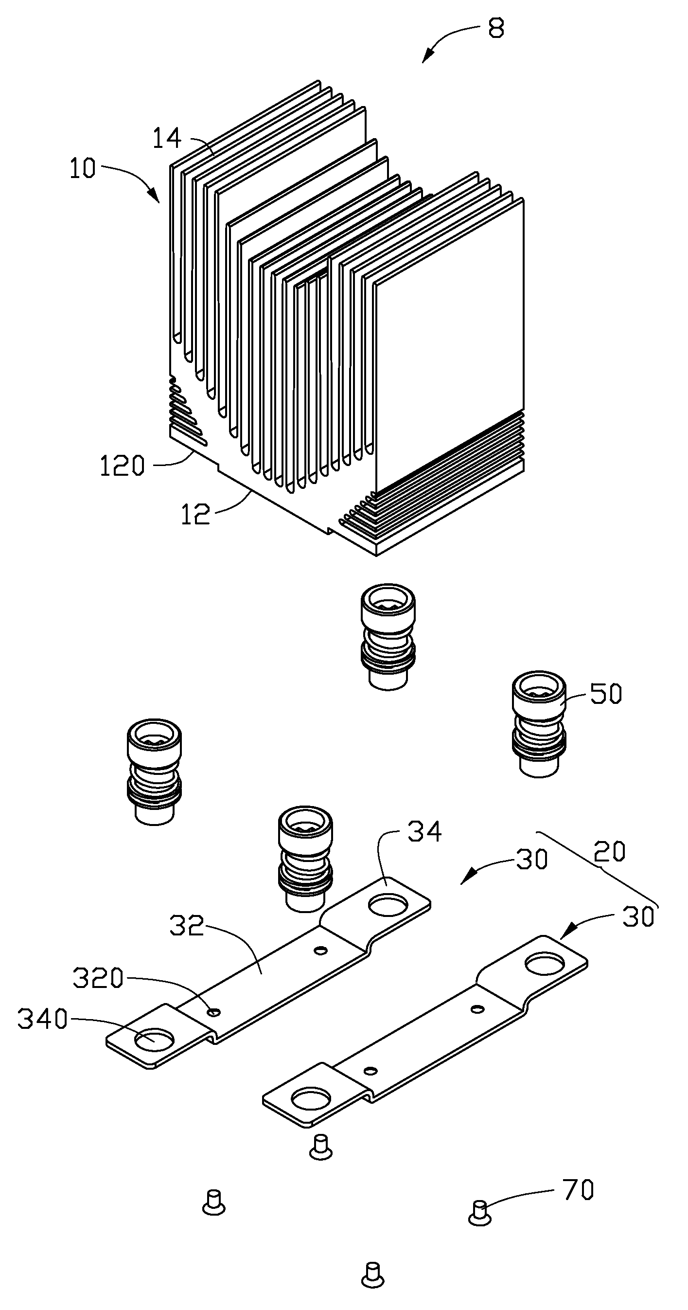
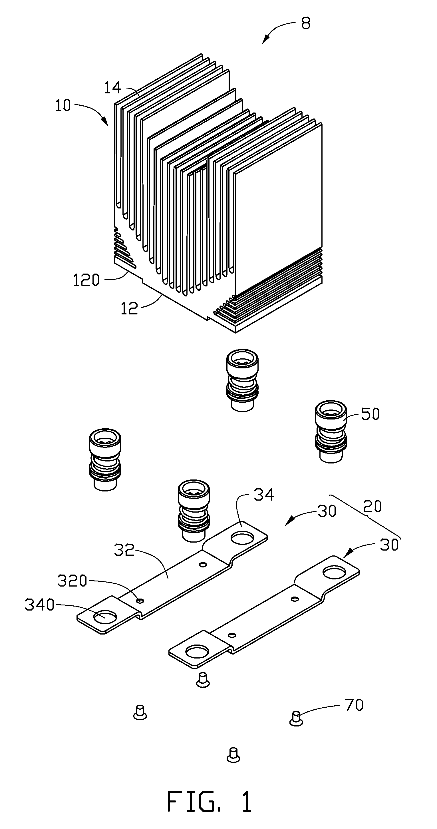
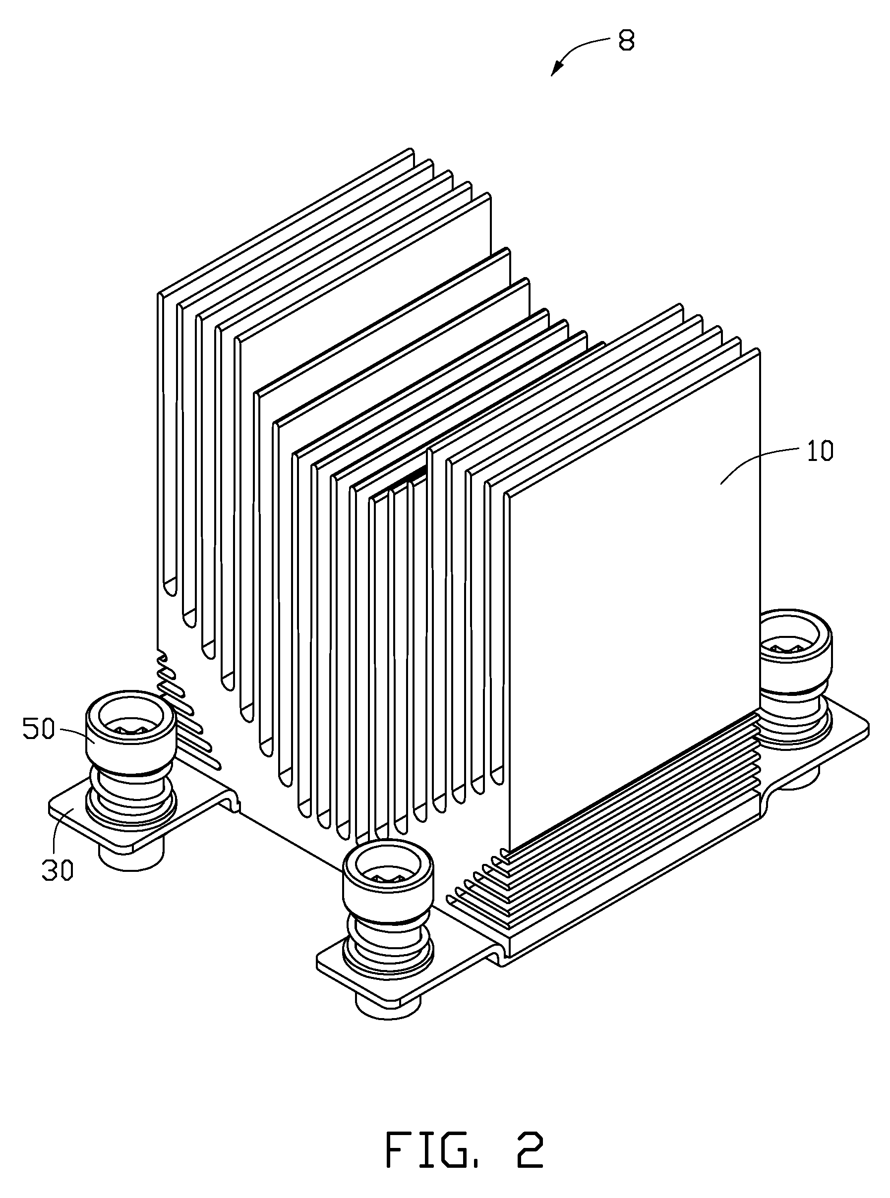
[0010]Referring to FIGS. 1 to 3, an embodiment of a heat sink 8 includes a cooling member 10, a fixing member 20, four fasteners 50, and four screws 70.

[0011]The cooling member 10 is used to dissipate heat for a component of an electronic device, such as a central processing unit of a motherboard. The cooling member 10 includes a rectangular flat base 12, and a plurality of fins 14 extending from a top of the base 12. Two grooves 120 are respectively defined in opposite ends of a bottom of the base 12. Two screw holes (not shown) are defined in a bottom of each of the grooves 120.

[0012]The fixing member 20 includes two separate metal fixing pieces 30. Each fixing piece 30 includes an elongated mounting portion 32 corresponding to one of the grooves 120 of the base 12, and two fastener mounts 34 respectively extending from opposite ends of the mounting portion 32. Each mounting portion 32 is located at a lower height than the corresponding fastener mounts 34, in order to match the co...


PUM

PropertyMeasurementUnit
heightaaaaaaaaaa
sizesaaaaaaaaaa
shapeaaaaaaaaaa

Abstract

A heat sink includes a cooling member to dissipate heat, and a fixing member for mounting fasteners. The cooling member includes a base and a number of fins extending from the base. The cooling member and the fixing member are independently formed, and the fixing member is fixed to a bottom of the base of the cooling member via fixing means.

Description

BACKGROUND[0001]1. Technical Field[0002]The present disclosure relates to a heat sink, and a method for manufacturing the heat sink.[0003]2. Description of Related Art[0004]A popular method for manufacturing a heat sink is: firstly, mold a semi-finished product, which includes a base and a number of fins extending from and covering the base; secondly cut away parts of the number of fins to expose a part of the base to form a fixing portion; thirdly, defines four through holes in the fixing portion; and last, install four fasteners in the through holes respectively. Thereby, the heat sink can be fixed to a circuit board via the fasteners for dissipating heat for a component of the circuit board. However, cutting the fins wastes material, which is uneconomical.BRIEF DESCRIPTION OF THE DRAWINGS[0005]FIG. 1 is an exploded, isometric view of a first embodiment of a heat sink, the heat sink including a fixing member.[0006]FIG. 2 is an assembled, isometric view of the heat sink of FIG. 1.[...

Claims


Application Information

Patent Timeline
Patent Type & Authority Applications(United States)
IPC IPC(8): H05K7/20B21D53/02F28F9/00
CPCH01L23/367H01L23/40H01L2924/0002Y10T29/4935Y10T24/42Y10T24/44556Y10T24/44034Y10T24/44026H01L2924/00
Inventor CHANG, YAO-TINGLIN, MENG-HSIENLAI, YU-CHIA
Owner HON HAI PRECISION IND CO LTD
Why Eureka
Try Eureka