
System and method for dynamic call routing

a dynamic call and call routing technology, applied in the field of system and method for dynamic call routing, can solve the problem that the storage requirements of network elements are small enough to be managed, and achieve the effect of reducing the number of calls and routing

Active Publication Date: 2010-10-14
GLOBAL CONVERGENCE SOLUTIONS
View PDF4 Cites 4 Cited by
  • Summary
  • Abstract
  • Description
  • Claims
  • Application Information

AI Technical Summary

Benefits of technology

[0008]Because the routing table uses only a small subset of data applicable to the call, the computations required for the routing table are minimal enough to be performed for each call. Because the data set from which the routing table is calculated is limited to that applicable for a particular call, the storage requirements in the network elements are similarly small enough to manage.

Problems solved by technology

Because the data set from which the routing table is calculated is limited to that applicable for a particular call, the storage requirements in the network elements are similarly small enough to manage.

Method used


Image

  • System and method for dynamic call routing
  • System and method for dynamic call routing
  • System and method for dynamic call routing

Examples


Embodiment Construction

[0016]In the following description, for purposes of explanation, specific numbers, materials and configurations are set forth in order to provide a thorough understanding of the invention. It will be apparent, however, to one having ordinary skill in the art that the invention may be practiced without these specific details. In some instances, well-known features may be omitted or simplified so as not to obscure the present invention. Furthermore, reference in the specification to phrases such as “one embodiment” or “an embodiment” means that a particular feature, structure or characteristic described in connection with the embodiment is included in at least one embodiment of the invention. The appearances of phrases such as “in one embodiment” or “in an embodiment” in various places in the specification do not necessarily all refer to the same embodiment.

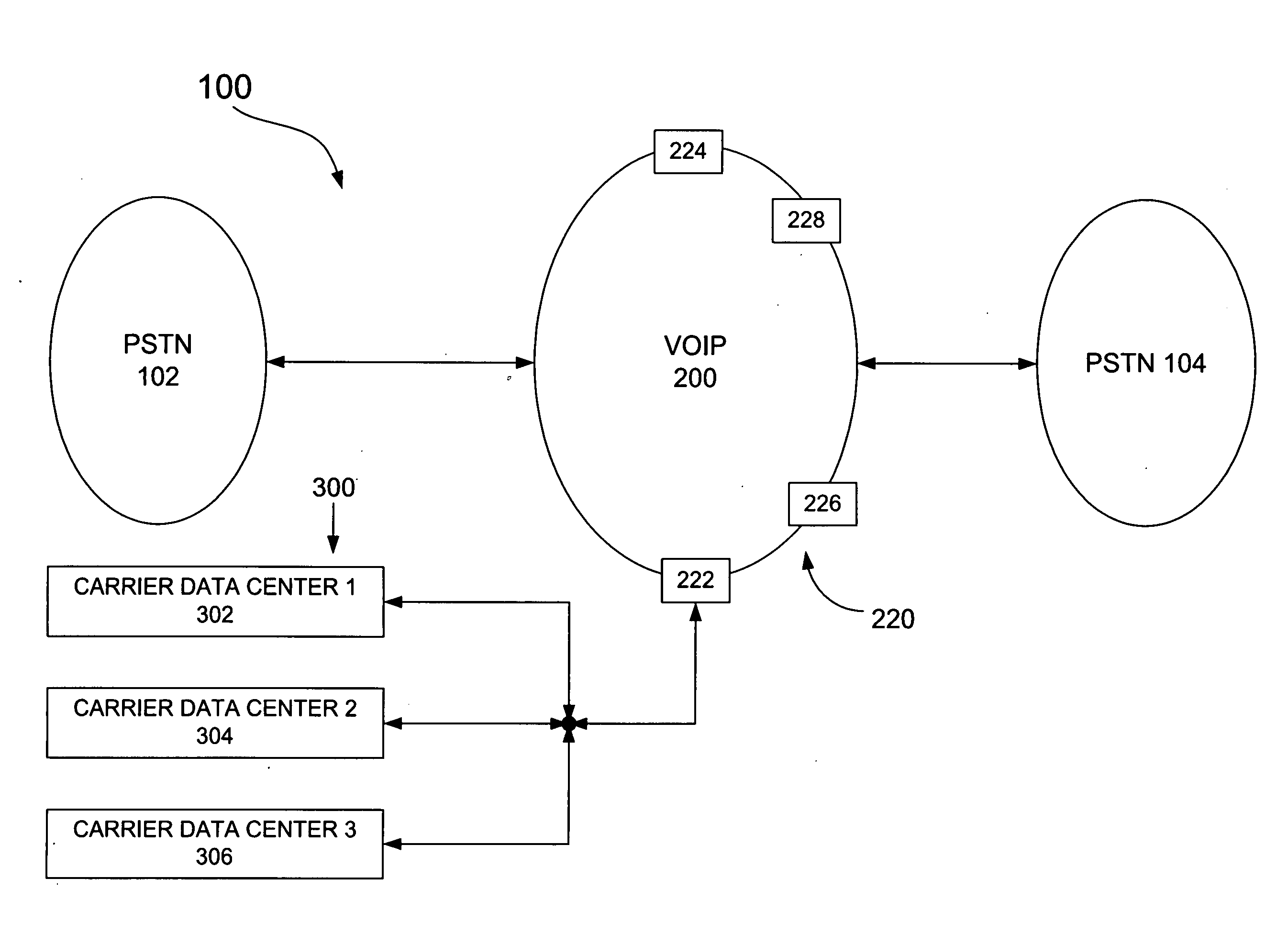
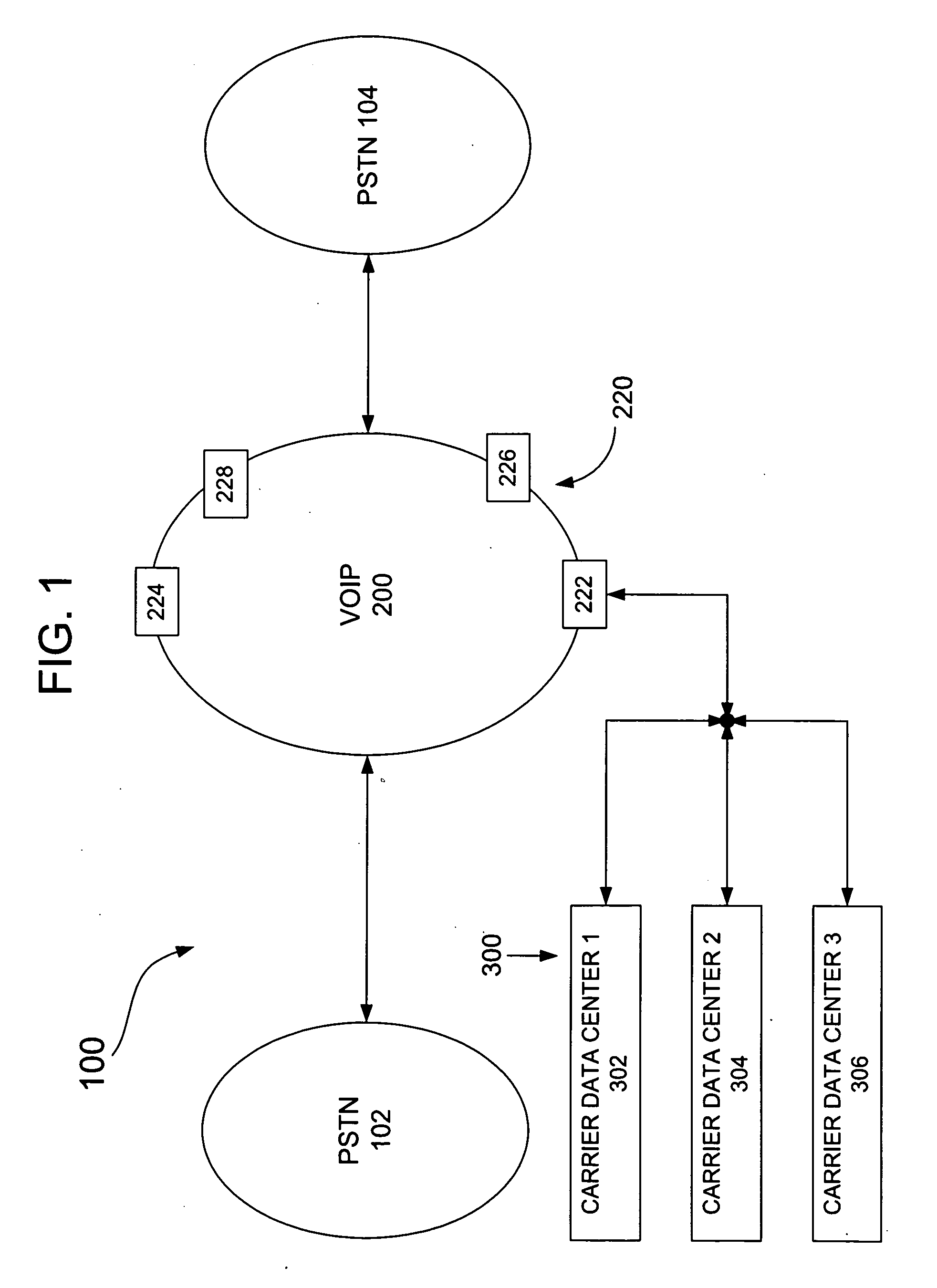
[0017]FIG. 1 is a block diagram of a system 100 for enabling calls to be transmitted from a origination PSTN network 102 to a des...


PUM


Abstract

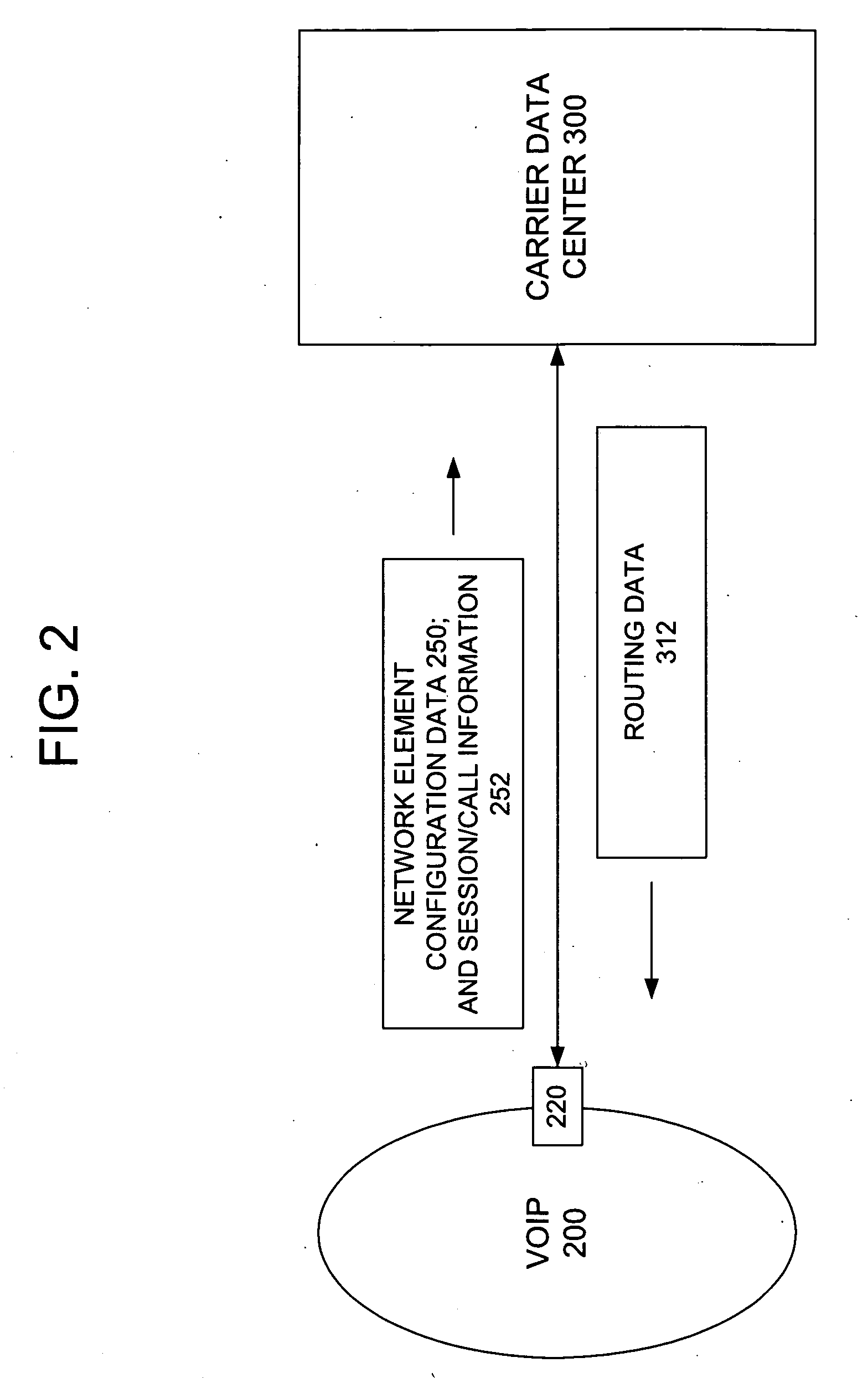
A telecommunications system is disclosed which may include a VOIP (Voice Over Internet Protocol) network having a plurality of network elements; at least one carrier data center; communication links enabling communication between the network elements and the at least one carrier data center, wherein the carrier data center is operable to receive a query describing a communication session active at a given one of the network elements, over one of the communication links, and to generate a routing table in response to the query.

Description

BACKGROUND OF THE INVENTION[0001]Voice Over Internet Protocol (VOIP) networks have been used to reduce the costs of long-distance telephone calling for several years. A call typically starts at an originating location within a traditional public circuit-switched telephone network (PSTN), interfaces with a VOIP network, then travels through the VOIP network, interfaces with a PSTN on the destination side of the VOIP network, and proceeds through the destination-side PSTN to a termination point to complete the call. Cost reduction is generally achieved by having the VOIP network service as large a part of the distance between the origination point and termination point of the call as possible.[0002]Some calls can be fully connected via the VOIP network, without the PSTN, but for purposes of explanation of the present invention, we assume the VOIP network interfaces to a PSTN, although the invention is not limited thereto.[0003]A call is typically routed through a sequence of intermedi...

Claims


Application Information

Patent Timeline
Patent Type & Authority Applications(United States)
IPC IPC(8): H04L12/66G06F17/30
CPCH04L45/3065H04L65/1083H04L65/1053H04M7/0075
Inventor MERANCHIK, JAY
Owner GLOBAL CONVERGENCE SOLUTIONS
Learn More