Method for setting a pixel clock of a display driving circuit

a display driving circuit and clock technology, applied in the field of setting a pixel clock, can solve the problems of inability to successfully apply different graphics cards, incompatibility of instructions defined in the basic input/output system of these different graphics cards, and inability to expand so as to reduce the amount of instructions in an associated program code, the effect of expanding the functionality of the display driving circuit and reducing the amount of stack capacity

Active Publication Date: 2007-03-20
VIA TECH INC
View PDF3 Cites 5 Cited by
  • Summary
  • Abstract
  • Description
  • Claims
  • Application Information

AI Technical Summary

Benefits of technology

[0017]It is an advantage of the claimed invention that the claimed method corresponds to minor computational complexity so that amount of instructions in an associated program code is greatly reduced. In other words, a basic input / output system of a display driving circuit is capable of accommodating other program codes used to expand functionality of the display driving circuit. In addition, amount of the stack capacity is also reduced owing to the minor computational complexity, and the reserved segments in the memory are protected from being occupied by the expanding stack capacity. Moreover, the unexpected crash problem is simultaneously solved according to the claimed method.

Problems solved by technology

Therefore, a compatibility problem existed among the graphics cards.
However, with regard to different graphics cards, instructions defined in the basic input / output systems of these different graphics cards are not compatible.
Therefore, the application was not capable of being applied to different graphics cards successfully.
As mentioned above, operation of the prior art corresponds to great computational complexity.
Therefore, program code associated with the clock setting procedure demands a great amount of instructions so that the memory capacity of the BIOS 26 is seriously occupied.
In other words, the BIOS 26 with a limited memory capacity is not capable of including additional program codes to expand functionality of the display driving circuit 16.
Therefore, an unexpected crash may occur on the computer device 10.
Therefore, if the calculation result CLKcal is represented by 32 bits, not only is the above calculation complicated, but also the stack makes use of a great amount of capacities.

Method used


Image

  • Method for setting a pixel clock of a display driving circuit
  • Method for setting a pixel clock of a display driving circuit
  • Method for setting a pixel clock of a display driving circuit

Examples


Embodiment Construction

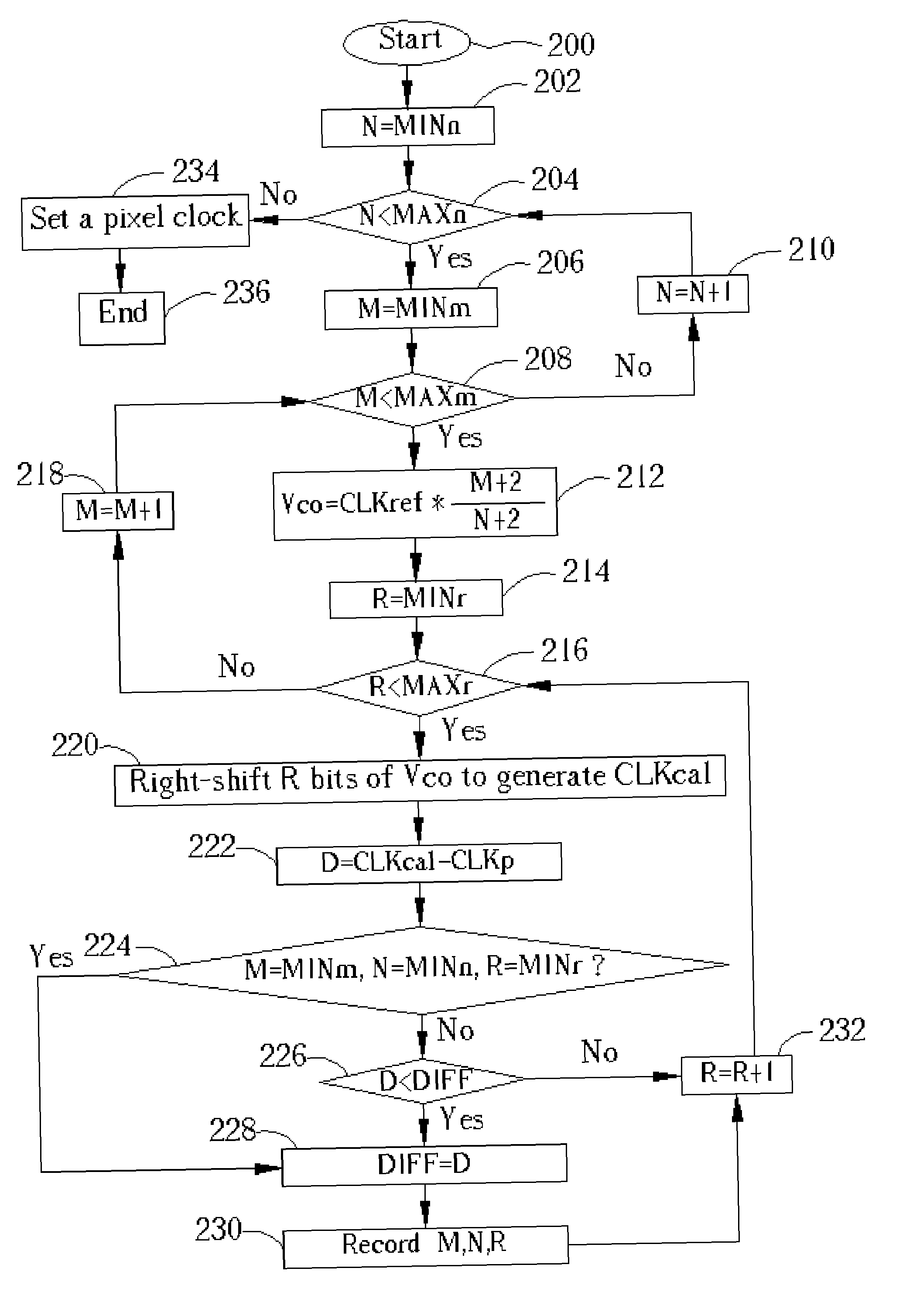
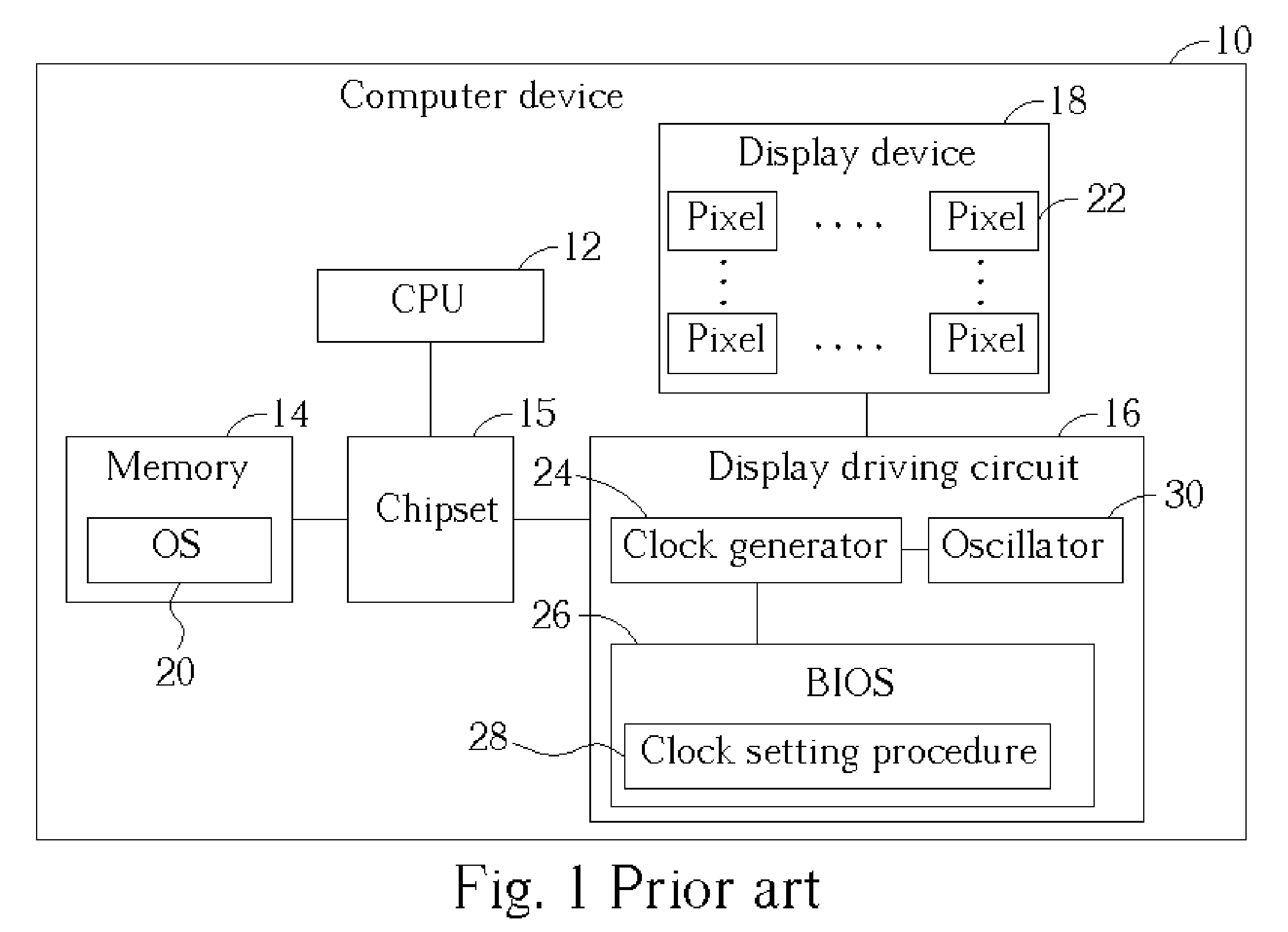
[0022]Please refer to FIG. 3 in conjunction with FIG. 1. FIG. 3 is a flow chart illustrating a method of setting the pixel clock. The method of setting the pixel clock is applied to the computer device 10 shown in FIG. 1, wherein the clock generator 24 is positioned inside a video chip. The display driving circuit 16 having the video chip is a graphics card or is positioned at a motherboard. In addition, functionality of components within the computer device 10 has been described previously. Therefore, the lengthy description is skipped for simplicity. The method of setting the pixel clock comprises following steps.

[0023]Step 200: Begin;

[0024]Step 202: Assign an initial value MINn to a value N;

[0025]Step 204: Determine whether the value N is less than a threshold value MAXn. If so, go to step 206; otherwise, jump to step 234;

[0026]Step 206: Assign an initial value MINm to a value M;

[0027]Step 208: Determine whether the value M is less than a threshold value MAXm. If so, go to step 2...


PUM


Abstract

A method for setting a pixel clock of a display driving circuit. The display driving circuit has a basic input/output system (BIOS) for controlling a clock generator to output the pixel clock. The method includes reading a predetermined pixel clock according to a display mode setting, utilizing a plurality of scaling factors to respectively adjust a reference clock for generating a plurality of calculation results, utilizing a plurality of coefficients R to respectively right-shift R bits of the calculation results for generating a plurality of quotients, comparing a plurality of differences between the quotients and the predetermined pixel clock for obtaining an optimum quotient, and controlling the clock generator to output an actual pixel clock according to the scaling factor and the coefficient R related to the optimum quotient.

Description

BACKGROUND OF INVENTION[0001]1. Field of the Invention[0002]The present invention relates to a method for setting a pixel clock. In particular, the present invention discloses a method for setting a pixel clock used by a display controller.[0003]2. Description of the Prior Art[0004]With popularization of computer devices, associated computer technology has been quickly developed to improve functionality and convenience of computer devices. Recently, operating speed of a central processing unit (CPU) has already exceeded one gigahertz (GHz), and the computer devices have powerful data processing capability now. Therefore, normal users do not merely view the computer devices as great helpers for work. The computer device increasingly becomes one of the entertainment facilities at home. In addition, with development and application of well-known multimedia technology, monitors and graphics cards of computer devices responsible for outputting videos become a major factor when consumers ...

Claims


Application Information

Patent Timeline
Patent Type & Authority Patents(United States)
IPC IPC(8): G09G5/00G06F3/14G09G5/18
CPCG06F3/14G09G5/18
Inventor WANG, CHIH-HAO
Owner VIA TECH INC
Why Eureka
Try Eureka