
Polyspectral Rangefinder for Close-In Target Ranging and Identification of Incoming Threats

a polyspectral rangefinder and target technology, applied in the direction of distance measurement, instruments, and using reradiation, can solve the problems of insufficient resolution of microwave radars to be able to pinpoint incoming missiles, inability to accurately identify incoming missiles, and inability to use radar to provide situational awareness in the immediate proximity of vehicles, etc., to achieve the effect of reducing the size of colored cells and greater resolution

Active Publication Date: 2008-11-06
BAE SYST INFORMATION & ELECTRONICS SYST INTERGRATION INC
View PDF5 Cites 26 Cited by
  • Summary
  • Abstract
  • Description
  • Claims
  • Application Information

AI Technical Summary

Benefits of technology

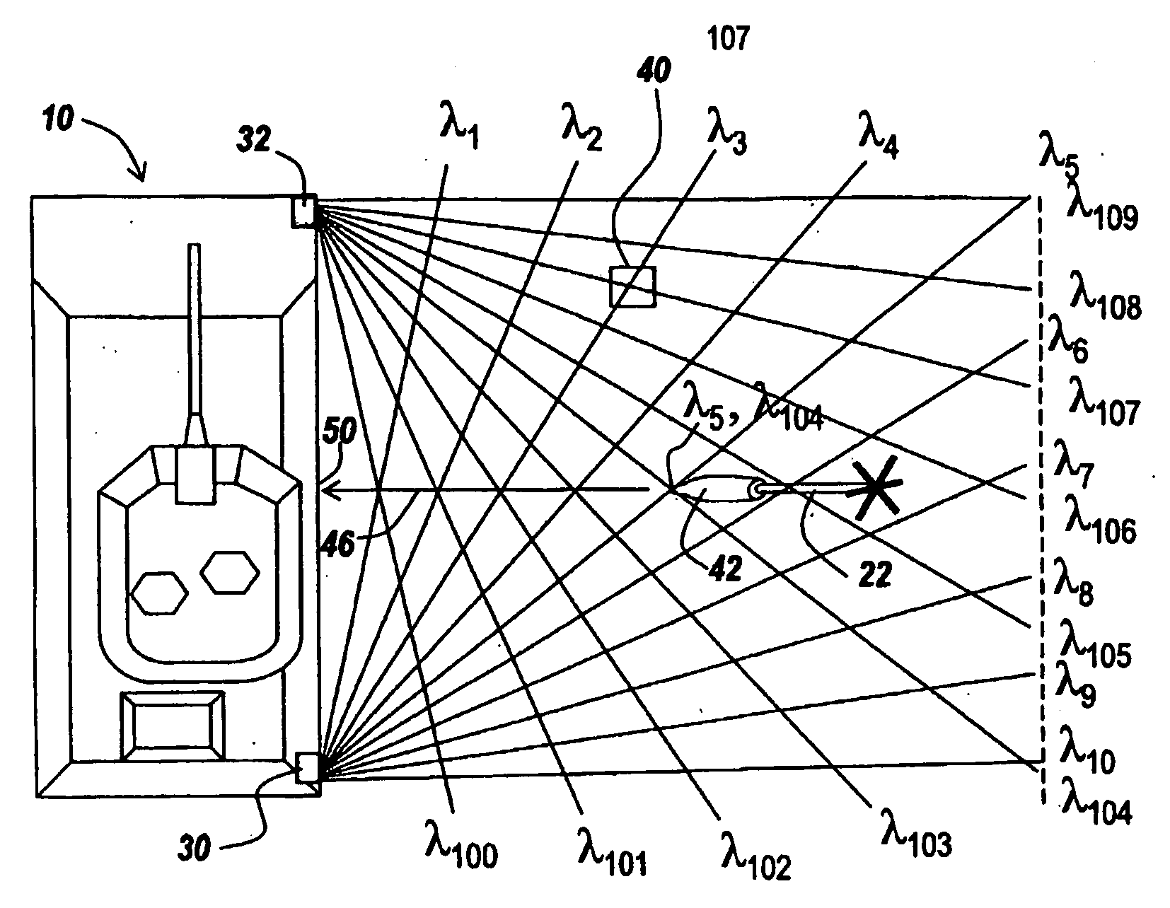
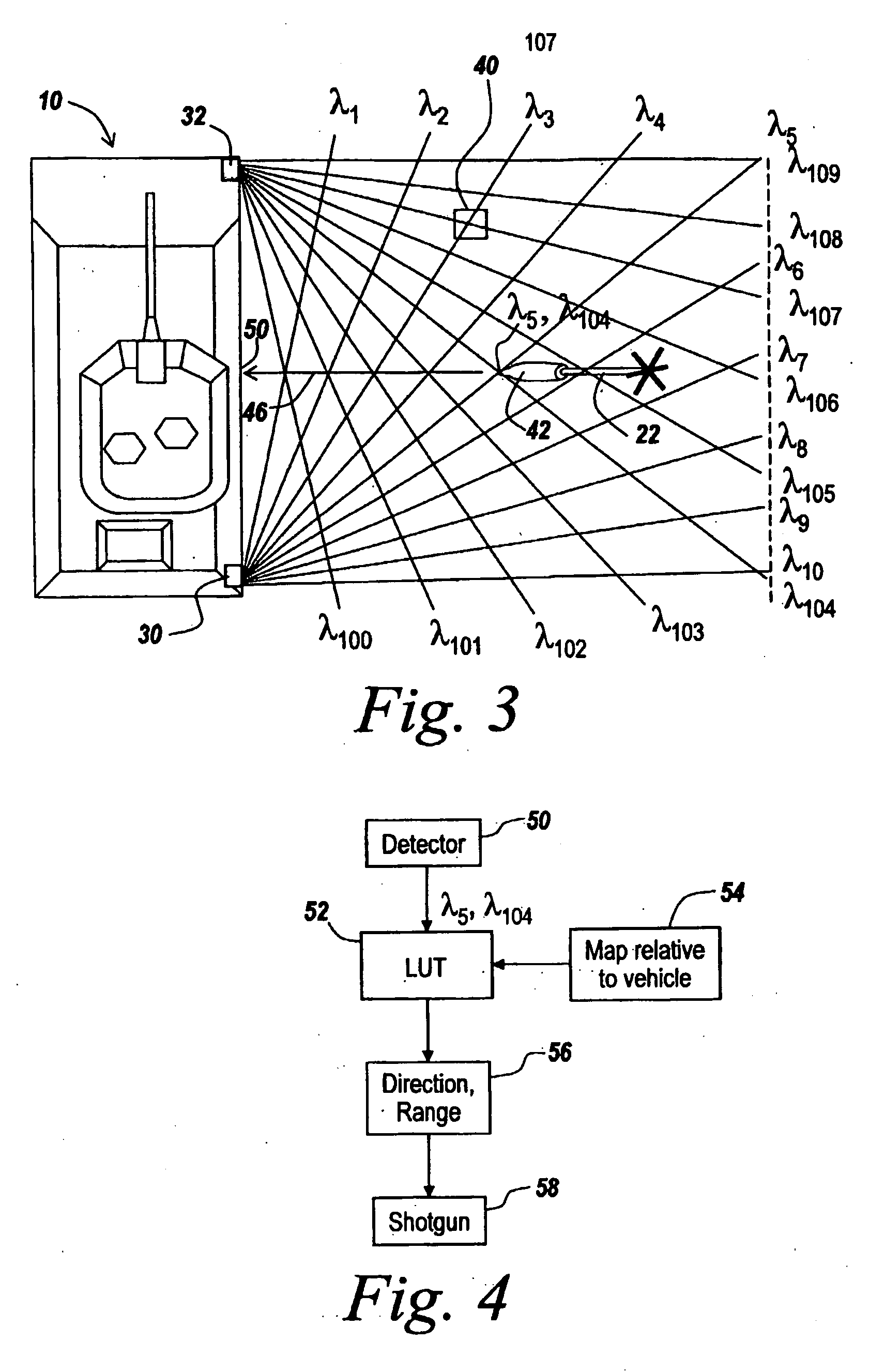
[0022]The detection of what colors are returned instantly determines, by virtue of the lookup table without computationally intensive algorithms, where the missile is. One then can direct countermeasures along the line from the place where the returns are sensed to the cell, thus to be able to countermeasure the incoming threat before it impacts the vehicle.
[0023]Since no computations are involved in locating the missile other than accessing a lookup table, detection of an incoming missile can be obtained in only a fraction of a second, virtually instantaneously. This permits rapid repositioning and firing, for instance, of a shotgun-type countermeasuring device.
[0024]It will also be appreciated that to minimize the size of the colored cells, one could increase the number of different colored fan beams projected, so that one could pre-map the area around the vehicle with greater resolution.
[0042]As will be appreciated, the subject invention minimizes the computing time for curing the countermeasure weapon because all that is necessary is to read out a lookup table. Note that by identifying the unique color cell, one instantly has the direction to the incoming ordnance from the lookup table. One therefore has provided a system for detecting incoming missiles that involves minimal computing so that one can respond more quickly to an incoming threat.

Problems solved by technology

This presents challenges not only to the countermeasure system in which one might, for instance, have to aim and fire a so-called shotgun in the direction of the incoming missile with a sufficiently dense pellet pattern but also to be able to detect and track where the incoming missile is in the first place.
While one could attempt to detect the launching of such a missile using radar, the use of radar to provide situational awareness in the immediate proximity of a vehicle suffers from a number of problems.
As will be appreciated, microwave radars might not have sufficient resolution to be able to pinpoint the incoming missile.
There is thus an associated scan time that may be much too long to permit effective countermeasuring of an incoming missile.
While such devices have tended to work well for the purpose of controlling fire directed against stationary or slow moving targets at a substantial range, these devices have limitations with respect to fast moving targets in close proximity to the sensing vehicle or structure.
This system, however, does not address the problem of detecting incoming projectiles or missiles that can be coming in from all directions.
Also it does not address the issue of computation time that is exceedingly short when it is necessary to detect and localize close-in missiles or projectiles.
While the prior devices have tended to work well for the purpose of controlling fire directed against stationary or slow moving targets at a substantial range, these devices may have limitations with respect to fast moving targets in close proximity to protected vehicles or personnel.

Method used


Image

  • Polyspectral Rangefinder for Close-In Target Ranging and Identification of Incoming Threats
  • Polyspectral Rangefinder for Close-In Target Ranging and Identification of Incoming Threats
  • Polyspectral Rangefinder for Close-In Target Ranging and Identification of Incoming Threats

Examples


Embodiment Construction

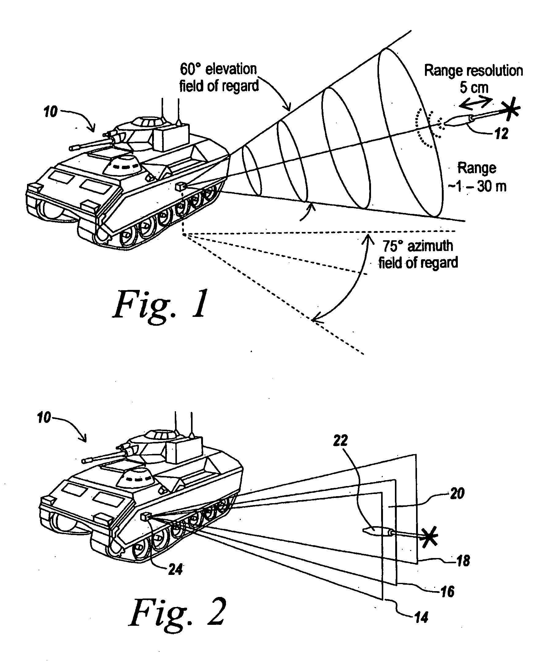
[0057]Referring now to FIG. 1, in order to be able to protect a vehicle 10 such as a tank from an incoming missile or ordnance 12 such as an rocket-propelled grenade or TOW missile, from a practical standpoint one needs, in one embodiment, 60° in elevation for a field of regard as well as 75° in azimuth for a field of regard. Thus, the surveilled area is divided up into 60° sections.

[0058]It is possible using standard techniques to cue a countermeasure module or system from conventional warning or tracking radar for crude or rough aiming, assuming a minimal time is spent in the rough positions of the countermeasure device. However, such conventional fire control systems may be too slow; and the subject system may be used in place of prior fire control systems. The subject system may thus be integrated into an active protection system, with the purpose to provide aim point refinement for close-in defensive rounds and to provide a target identification, i.e., an RPG, TOW missile or a ...


PUM


Abstract

A computationless system 10 is provided for determining the direction of and distance to a target 42, involving bathing an area surrounding an area to be protected with a polyspectral series of narrow fan beams (xi,)ioo) of different colors from at least two spaced-apart projectors 30, 32. The differently colored beams go out at different angles, thus to color-code map the area surrounding the protected space where beams of different colors cross to form color-coded cells. Light 46 reflected back to the area to be protected from a threat 42 has a color code corresponding to the colors associated with beams that cross at the threat, thus to identify by the reflected colors where in space the threat is located.

Description

RELATED APPLICATIONS[0001]This application claims rights under 35 USC § 119(e) from U.S. Application Ser. No. 60 / 560,004 filed Apr. 6, 2004, the contents of which are incorporated herein by reference.FIELD OF THE INVENTION[0002]This invention relates to the detection and localization of incoming missiles or other ordinances and more particularly to a system for rapid identification of and ranging to close-in targets.BACKGROUND OF THE INVENTION[0003]In combat situations, or in situations in which troops and vehicles are deployed for policing purposes, combat vehicles and personnel are subject to attack at very close range through the use of rocket-propelled grenades (RPGs) or other ordinances which are launched from sites which are very close to the personnel or vehicles. Thus, troops and vehicles are subject to weapons launched in their immediate vicinity. There is therefore a need to be able to detect an incoming missile and to countermeasure it all within the space of, for instanc...

Claims


Application Information

Patent Timeline
Patent Type & Authority Applications(United States)
IPC IPC(8): G01C3/08
CPCF41G3/14F41G5/08F41H11/02G01B11/026G01C3/06G01S17/46G01S17/87
Inventor SMITH, M. JAMES
Owner BAE SYST INFORMATION & ELECTRONICS SYST INTERGRATION INC
Learn More