
Combination of Bicycle Rear Wheel Hub and Sprocket Set

Inactive Publication Date: 2010-10-14
JOY IND
View PDF4 Cites 41 Cited by
  • Summary
  • Abstract
  • Description
  • Claims
  • Application Information

AI Technical Summary

Benefits of technology

[0011]Another object of the present invention is to provide a connection tube on the rear wheel hub wherein the manufacturing cost of the connection tube is significantly reduced because only the driving surface contacts the engaging rib of the sprocket set.

Problems solved by technology

However, the direction of rotation of the sprocket set 80 is fixed so that only the inside “A” of the recess 851 actually transfers the force, and the other inside “B” does not provide such function.
The assemblers have to check carefully for the engagement of the protrusions 83 and the recesses 851 and this increases the time required and the cost of labor cost.

Method used


Image

  • Combination of Bicycle Rear Wheel Hub and Sprocket Set
  • Combination of Bicycle Rear Wheel Hub and Sprocket Set
  • Combination of Bicycle Rear Wheel Hub and Sprocket Set

Examples


Embodiment Construction

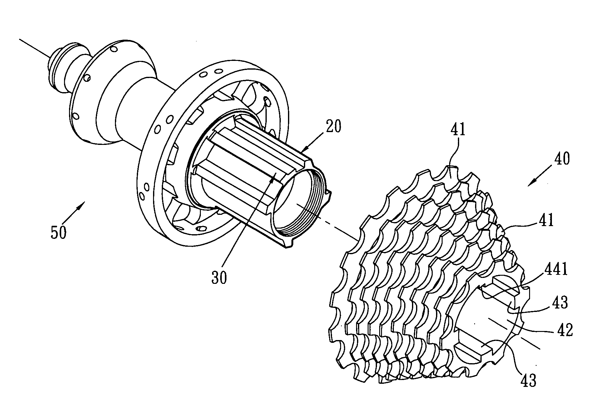
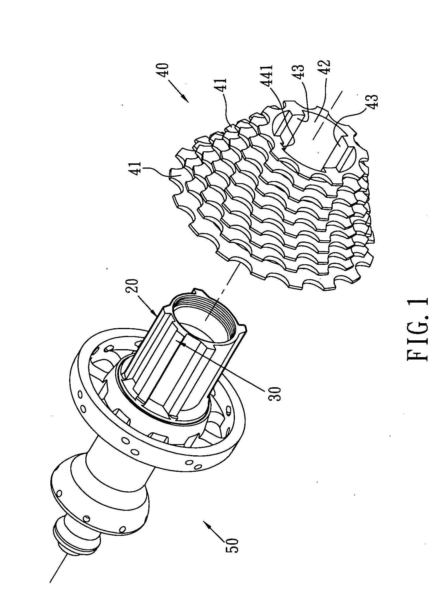
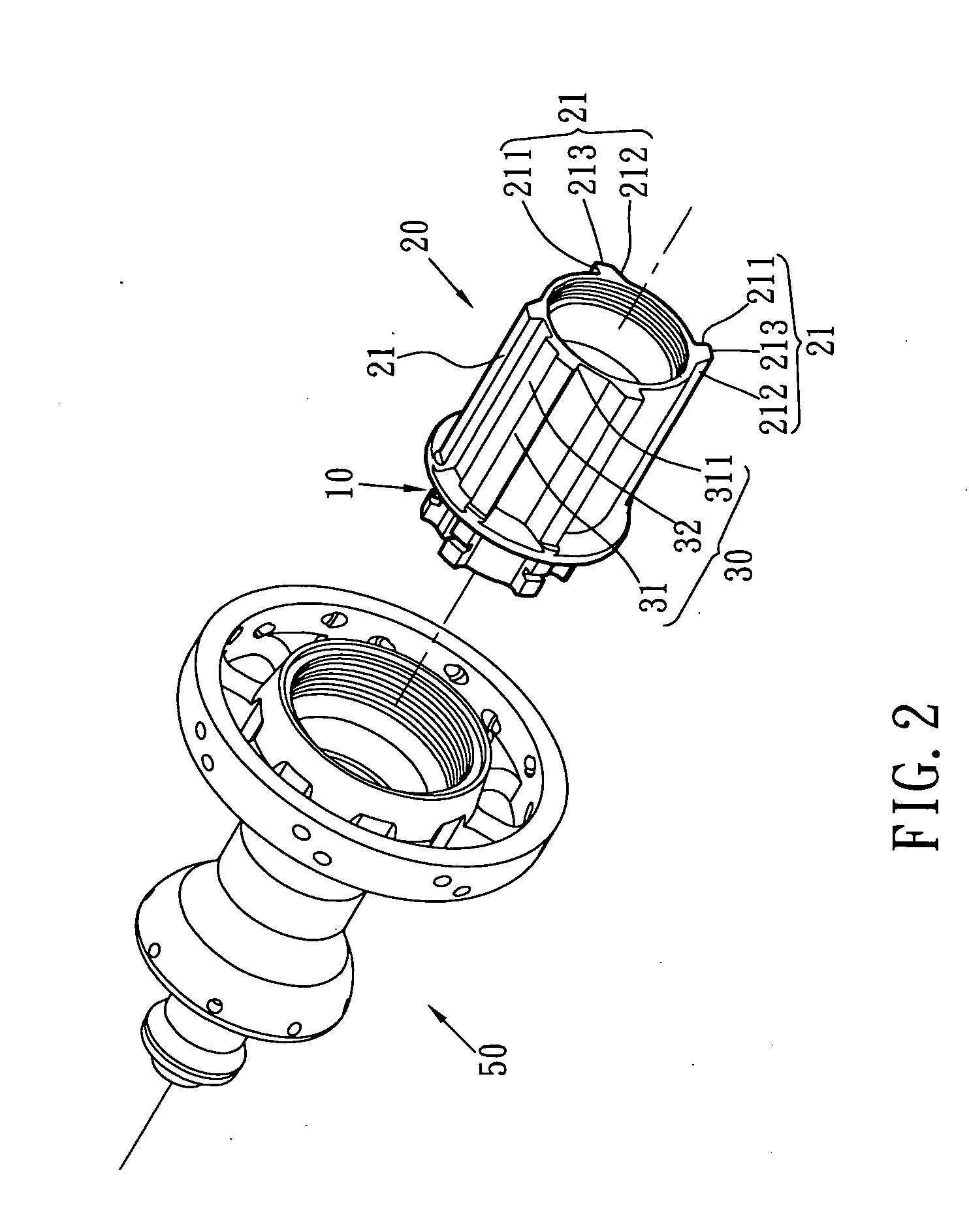
[0023]Referring to FIGS. 1 to 5, the connection tube of bicycle rear wheel hub of the present invention comprises a connection portion 10 extending axially from a first end thereof and an engaging portion 20 extends axially from a second end of the connection tube. The connection portion 10 is connected with one end of the rear wheel hub 50. The engaging portion 20 extends from the end of the rear wheel hub 50 and is a hollow tube. Four driving ribs 21 extend radially from an outer periphety of the engaging portion 20, and the driving ribs 21 are located axially on the engaging portion 20. Each driving rib 21 includes a driving surface 211 and an inclined surface 212 on two sides thereof. A crown surface 213 is connected between the driving surface 211 and the inclined surface 212 of each driving rib 21. The driving surface 211 is perpendicular to the outer periphery of the engaging portion 20 and the inclined surface 212 is inclined relative to the outer periphery of the engaging p...


PUM


Abstract

A connection tube of bicycle rear wheel hub includes a connection portion and an engaging portion one two ends of the connection tube, the connection portion is connected to the bicycle rear wheel hub. The engaging portion is a hollow tube and four elongate driving ribs extend radially from an outer periphery of the engaging portion. Each driving rib includes a driving surface and an inclined surface on two sides thereof. The driving surface is perpendicular to the outer periphery of the engaging portion. A positioning rib extends radially from an outer periphery of the engaging portion and is located between two driving ribs. Only the driving surface contacts the engaging ribs of the sprocket set.

Description

FIELD OF THE INVENTION[0001]The present invention relates to a bicycle rear hub and more particularly, to an engaging portion on a bicycle rear hub rear wheel hub so as to be connected with a CAMPAGNOLO sprocket set.BACKGROUND OF THE INVENTION[0002]A conventional derailleur system for bicycle generally includes at least one chain ring connected with the crank, a sprocket set connected to one end of the rear wheel hub, and a chain which transfers the driving force from the chain ring to one of the sprockets of the sprocket set. Generally, the sprocket set includes 5 to 10 sprockets of different number of teeth and the shifting mechanism of the derailleur system shifts the chain from one sprocket to another so as to obtain desired speed.[0003]There are two main brand names for the connection tubes of the rear wheel hubs, which are SHIMANO and CAMPAGNOLO, the difference between the connection tubes of the two brands is the engaging portion on the rear wheel hub.[0004]As shown in FIG. 9...

Claims


Application Information

Patent Timeline
IPC IPC(8): B25G3/28B60B27/00
CPCB60B27/023Y10T403/7026B60B27/04B62M9/121
Inventor CHIANG, PI-YUN
Owner JOY IND
Learn More