Eureka AIR delivers breakthrough ideas for toughest innovation challenges, trusted by R&D personnel around the world.

Vessel for laying a pipeline and comprising an a & r means

Inactive Publication Date: 2010-10-14
HEEREMA MARINE CONTRACTORS NEDERLAND SE
View PDF6 Cites 4 Cited by
  • Summary
  • Abstract
  • Description
  • Claims
  • Application Information

AI Technical Summary

Benefits of technology

[0007]An object of the invention is to provide a vessel which allows a faster preparation of the vessel for bad weather or for operation after bad weather.

Problems solved by technology

This means that the pipeline has to be abandoned from the vessel by positioning the pipeline on the seabed.
Said preparation of the vessel for bad weather is a time consuming operation.
This means that the preparation of the vessel for bad weather or for resuming an operation after bad weather is very time consuming.
Due to this, costly operational time in which pipeline can be laid is lost.
Furthermore, due to the fact that the preparation of the vessel for bad weather is very time consuming, said preparation has to be started long before the bad weather is expected to arrive.
Many hours of operational time often lost this way.

Method used


Image

  • Vessel for laying a pipeline and comprising an a & r means
  • Vessel for laying a pipeline and comprising an a & r means
  • Vessel for laying a pipeline and comprising an a & r means

Examples


Embodiment Construction

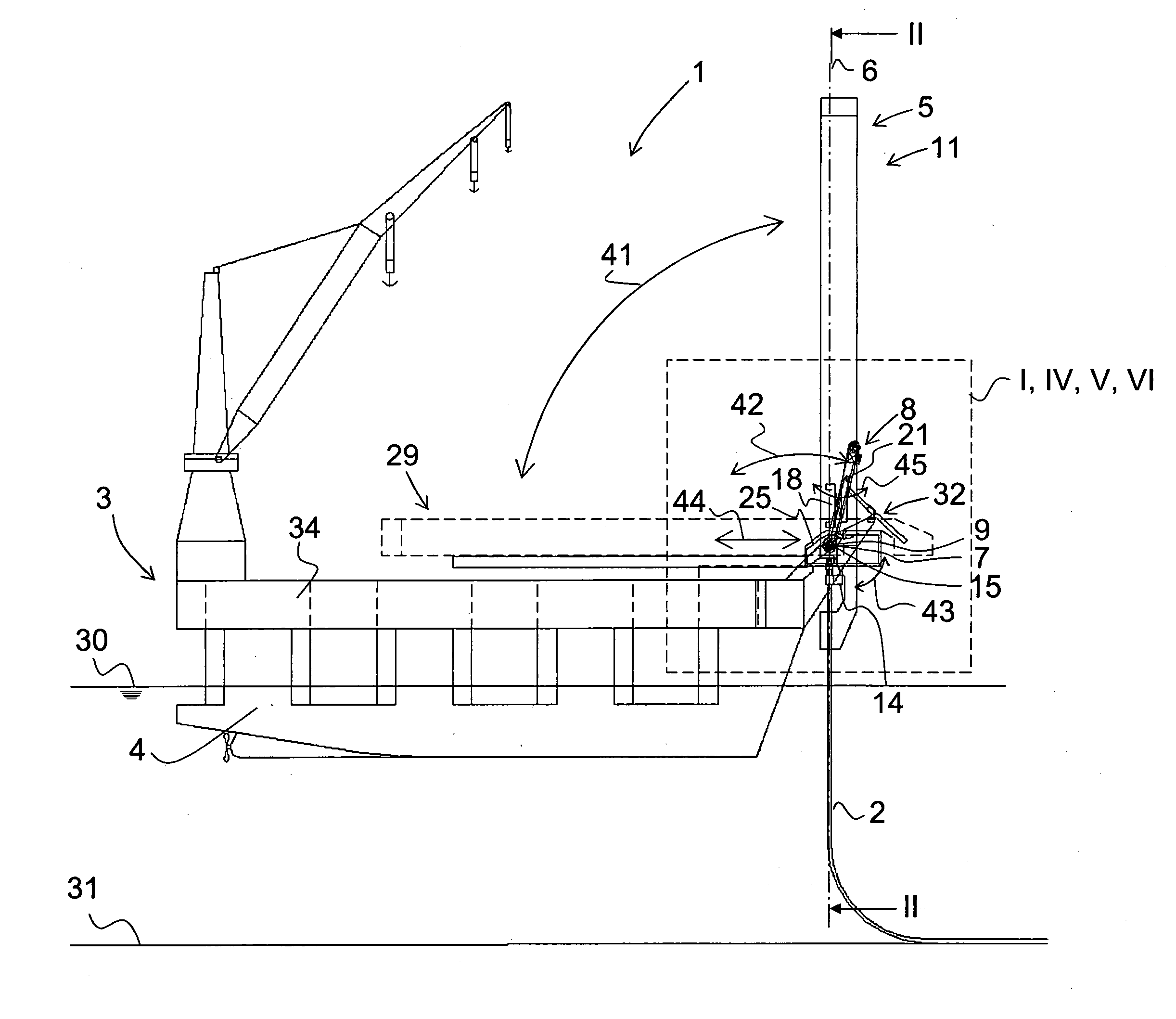
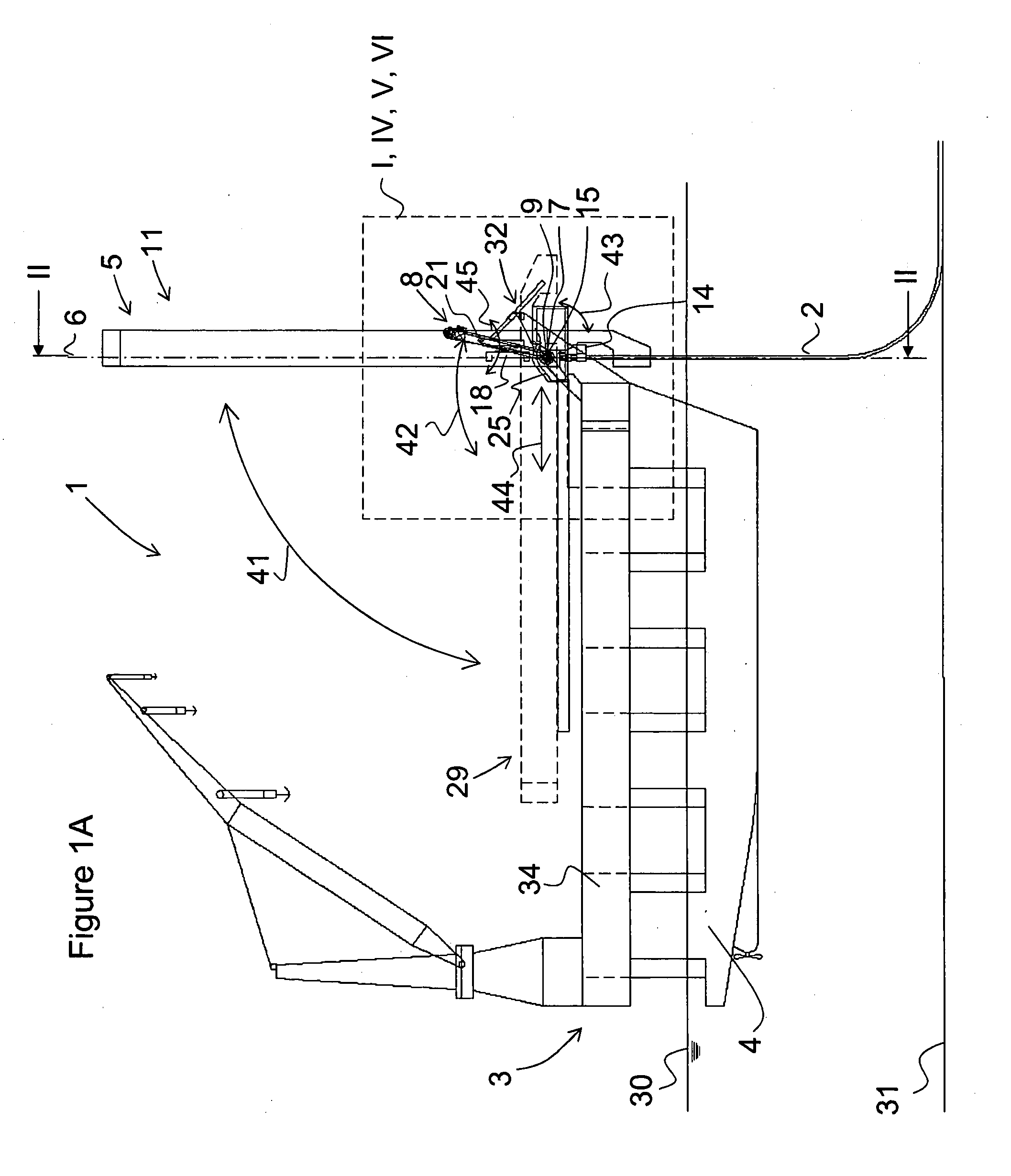
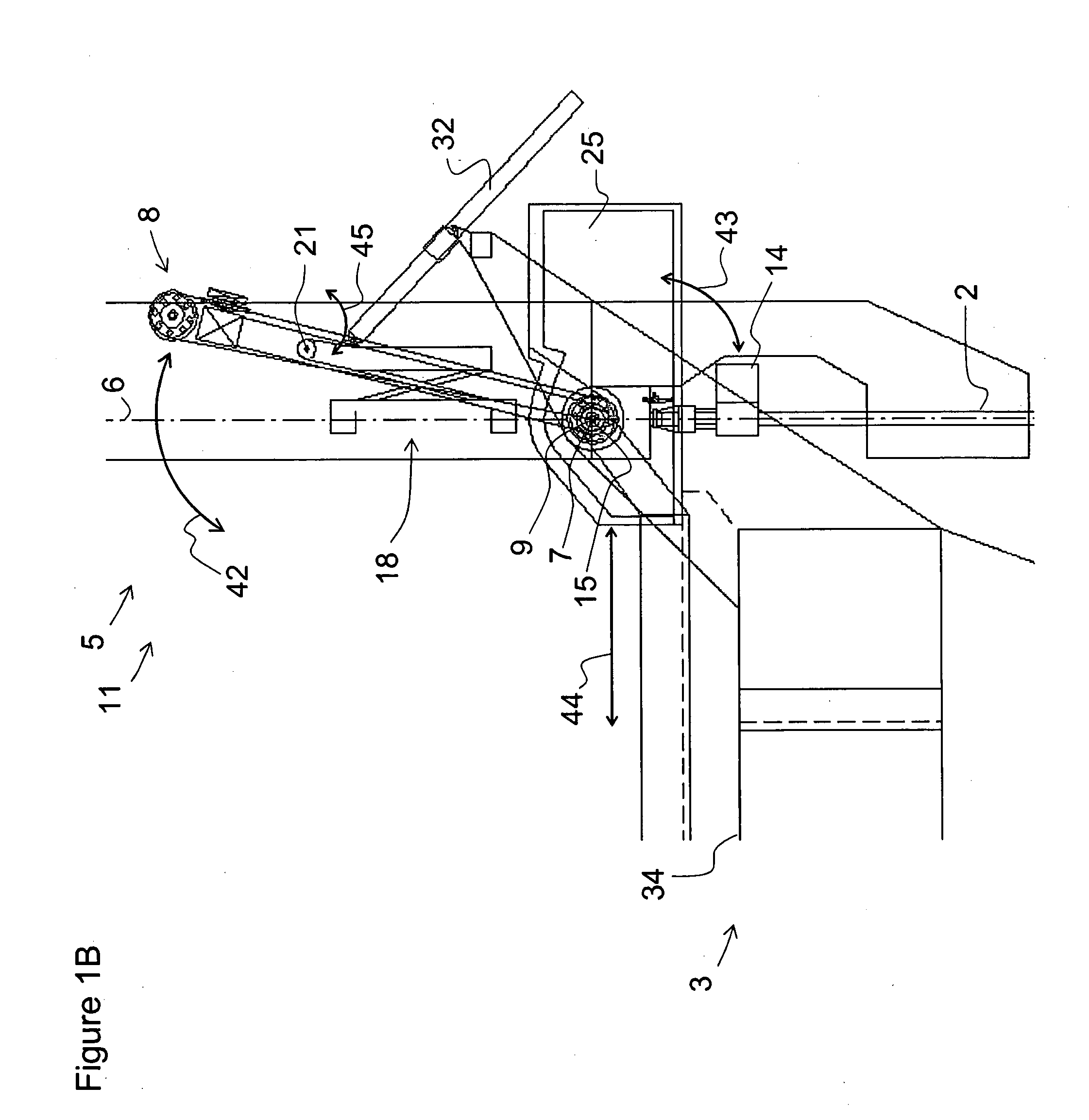
[0030]FIGS. 1A and / or 1B show an embodiment of a vessel according the invention, the water line 30 and the sea bed 31. The vessel 1 is used for the laying of a pipeline 2. The vessel 1 comprises a hull structure 3 with two floaters 4, and a deck 34 positioned on top of those floaters 4. A tower 5 is positioned at the bow of vessel 1. The tower 5 is positioned in a pipelaying position 11 in which it defines a firing line 6 along which the pipeline 2 is laid. During pipelaying, the pipeline 2 is constructed from pipe sections and leaves the tower 5 along the firing line 6. The pipelaying position 11 of the tower 5 is determined by the pipe departure angle. The tower 5 is pivotable connected to the vessel 1 such that the tower 5 can pivot relative to the hull structure 3 about a tower pivot axis 7. The pivot movement of the tower 5 is indicated by arrow 41. The tower 5 may be lowered from said pipelaying position to the deck 34 into a laid down position 29. Said pivot movement of the t...


PUM


Abstract

A vessel (1) for laying a pipeline, the vessel comprising a hull structure (3) comprising one or more floaters (4), a tower (5) defining a firing line (6) when positioned in a pipelaying position, the tower (5) being pivotable relative to the hull structure (3) about a tower pivot axis (7), and an A & R means (8) for abandoning and / or recovering the pipeline, wherein the tower (5) is pivotable about said tower pivot axis (7) substantially independent from the A & R means (8) and the A & R means (8) is configured to operate while the tower (5) is pivoted about said tower pivot axis (7).

Description

CROSS-REFERENCE TO RELATED APPLICATIONS[0001]This application is the National Stage of International Application No. PCT / NL2007 / 000327, filed Dec. 21, 2007, the contents of which is incorporated by reference herein.FIELD OF THE INVENTION[0002]The invention relates to a vessel for laying a pipeline, the vessel comprising a hull structure comprising one or more floaters, a tower defining a firing line when positioned in a pipelaying position, the tower being pivotable relative to the hull structure about a tower pivot axis, and an A&R means for abandoning and / or recovering the pipeline. The firing line is the line along which the pipeline is lowered to a seabed. The tower positioned in the pipelaying position defines the firing line. During pipelaying, the pipeline leaves the tower along the firing line.BACKGROUND OF THE INVENTION[0003]Such a vessel is known from the prior art. During the laying of the pipeline the tower is positioned in an upright position, with an angle relative to ...

Claims


Application Information

Patent Timeline
IPC IPC(8): F16L1/12
CPCB63B35/03F16L1/207F16L1/202F16L1/19
Inventor HILLENAAR, MAIKELVAN GRIEKEN, GERARDUS CORNELIUS
Owner HEEREMA MARINE CONTRACTORS NEDERLAND SE
Why Eureka
Eureka Blog
Learn More