Wire coupling device

Inactive Publication Date: 2010-10-14
HALEXSCOTT FETZER
View PDF5 Cites 0 Cited by
  • Summary
  • Abstract
  • Description
  • Claims
  • Application Information

AI Technical Summary

Benefits of technology

[0011]One advantage of this invention is that for joining electrical wires it reduces the number of tools, and eliminates specialized tools that electricians need to carry.
[0013]Yet another advantage of this invention is that it provides a simple to use and reliable device to join two or more separate electrical wires.

Problems solved by technology

However, the splicing method requires use of specialized crimping tools, and the in-line methods require use of a standard wrench or a hex wrench.
It is inconvenient for an electrician to carry additional crimping equipment or wrenches.
Similarly, it is inefficient to stop the process of installing wire to join the separate wires together using a wrench.

Method used


Image

  • Wire coupling device
  • Wire coupling device
  • Wire coupling device

Examples


Embodiment Construction

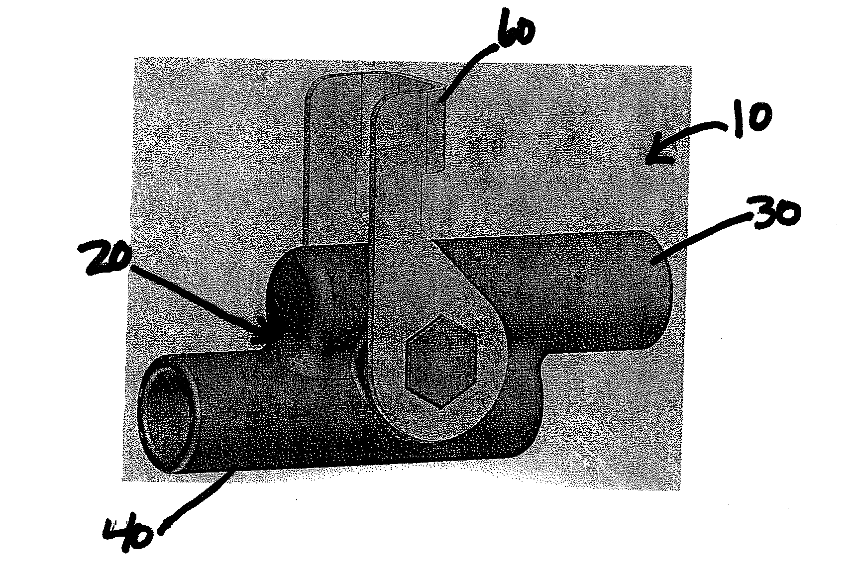
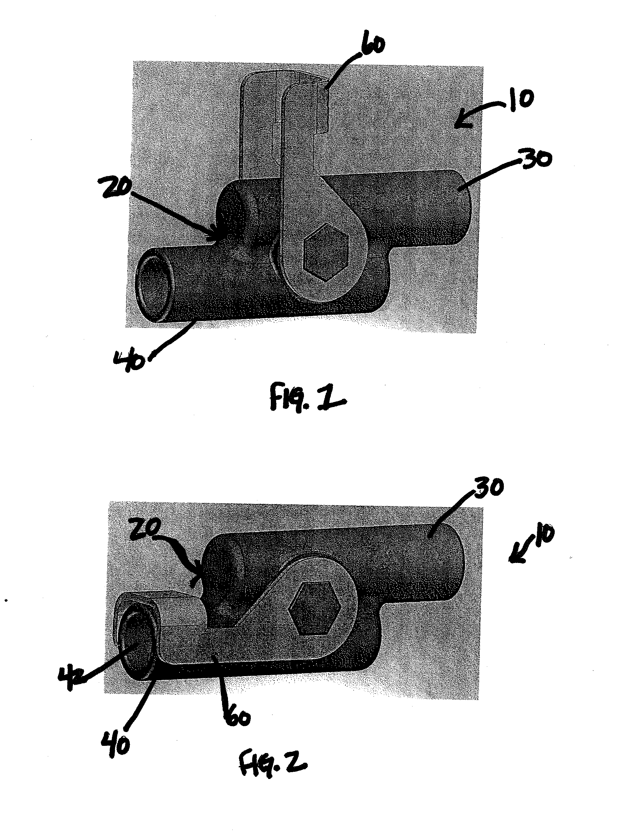
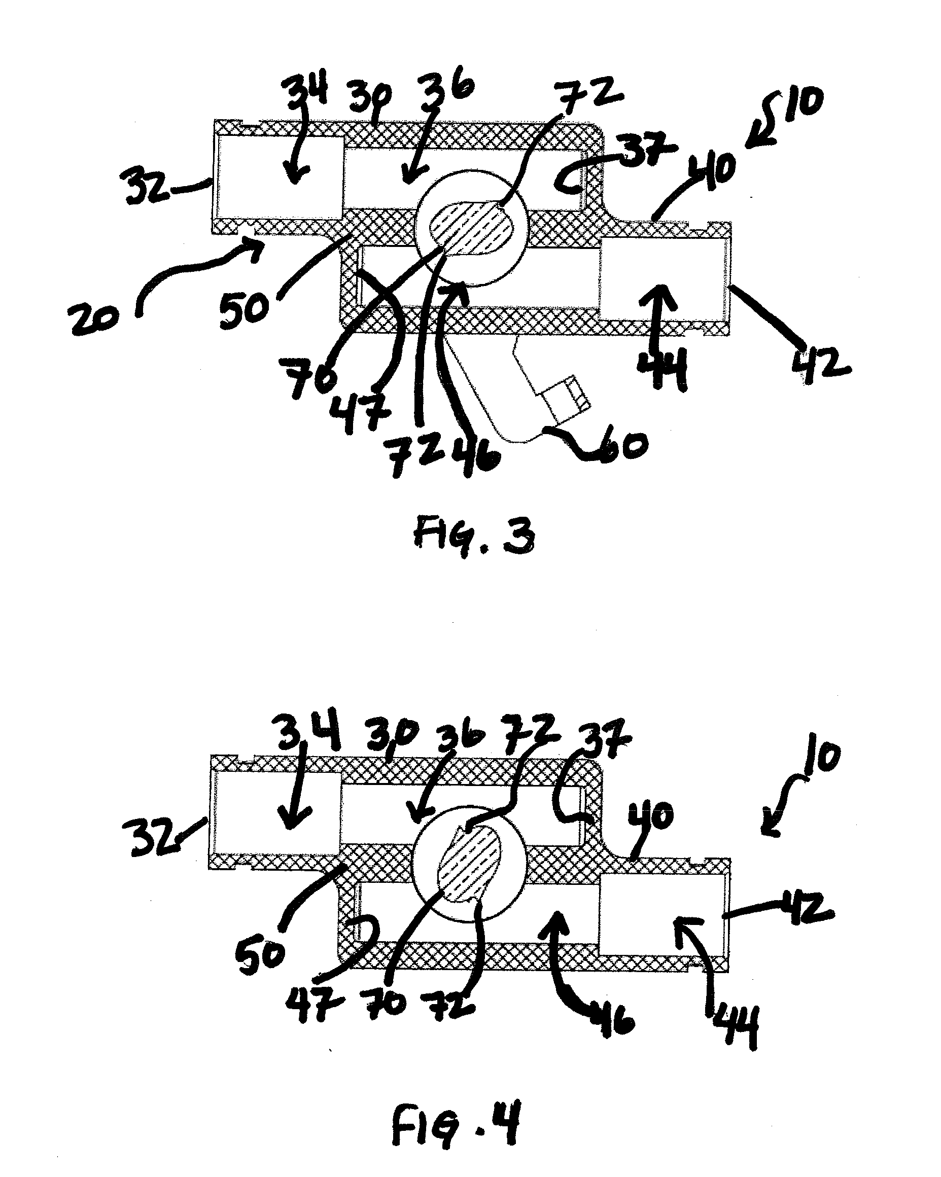
[0024]Referring now to the drawings wherein the showings are for purposes of illustrating embodiments of the invention only and not for purposes of limiting the same, and wherein like reference numerals are understood to refer to like components, FIGS. 1-5 show a wire coupling device 10 that comprise a housing 20 which includes a first port 30 and a second port 40. In construction, the housing 20 may comprise a material that does not conduct electricity, or may have an interior that is insulated with non-conductive material. The longitudinal axes of ports 30, 40 may be parallel but spaced apart in the same plane and may be separated by a separating member 50. Of course, any other parallel or non-parallel arrangement may also be designed and utilized for particular desired situations. The device 10 may further include a lever 60 operably attached to a camming mechanism 70. The camming mechanism 70 may be disposed through the housing 20 and the separating member 50, and, such as in th...


PUM

PropertyMeasurementUnit
Timeaaaaaaaaaa
Angleaaaaaaaaaa
Angleaaaaaaaaaa

Abstract

A wire coupling device which may be used joining at least a separate first wire and second wire comprising: a housing having at least a first port and a second port, each port configured to receive a separate wire; a camming member disposed between the at least first and second ports, the camming member rotatable between a first, open position and a second, closed position, where the camming member provides electrical contact between the at least first wire and second wire when in the second, closed position.

Description

[0001]This application claims priority to U.S. Ser. No. 61 / 169,050, entitled WIRE COUPLING DEVICE, filed Apr. 14, 2009, which is incorporated herein by reference.I. BACKGROUND[0002]A. Field of Invention[0003]This invention generally relates to methods and apparatuses concerning installation of utility lines and more specifically relates to methods and apparatuses concerning joining in electrical communication two or more separate lines.[0004]B. Description of the Related Art[0005]It is well known to utilize splicing and in-line wire couplings devices to join separate electrical wires or lines to provide electrical communication.[0006]Known coupling devices may use bolts or set screws to secure the electrical lines. However, the splicing method requires use of specialized crimping tools, and the in-line methods require use of a standard wrench or a hex wrench. It is inconvenient for an electrician to carry additional crimping equipment or wrenches. Similarly, it is inefficient to sto...

Claims


Application Information

Patent Timeline
IPC IPC(8): H01R4/50H01R4/24H01R13/52H01R43/00
CPCH01R4/26H01R4/5008Y10T29/49194H01R13/52H01R9/24
Inventor GARDNER, MICHAEL J.BAKER, GLENN A.
Owner HALEXSCOTT FETZER
Why Eureka
Try Eureka