Low cost coaxial cable connector for multiple cable sizes

a coaxial cable and cable connector technology, applied in the direction of connections, metal working devices, manufacturing tools, etc., can solve the problems of high cost of compression-type cable connectors, requiring a more complex corresponding compression tool, and generally not being used by homeowners, and achieves simple and inexpensive construction. the effect of low cos

Inactive Publication Date: 2010-10-14
PPC BROADBAND INC
View PDF17 Cites 25 Cited by
  • Summary
  • Abstract
  • Description
  • Claims
  • Application Information

AI Technical Summary

Benefits of technology

[0019]The present invention meets this need by providing a coaxial cable connector for connecting a coaxial cable to an RF port, wherein the cable connector is comprised of a connector subassembly and a compression cap. The connector subassembly is of simple inexpensive construction, and may function a stand-alone crimpable cable connector. The compression cap may be placed over the end of a coaxial cable, and compressed onto the connector subassembly to secure a prepared end of the cable within the compressed and assembled connector. The compression cap may be made using a simple molding process and mold tooling, and is thus inexpensive. Accordingly, the combination of the compression cap and the connector subassembly provides a coaxial cable compression-type connector at low cost.

Problems solved by technology

Compression-type cable connectors are significantly more expensive than crimp type connectors, and also require a more complex corresponding compression tool.
Although compression connectors provide a connection with a higher quality signal and greater moisture resistance, they are generally not used by homeowners due the their higher cost.
This often presents problems for inexperienced installers (such as homeowners) in terms of consistent quality of termination.
This is because the compression ring or ferrule of the compression sleeve does not undergo a sufficient reduction in inner diameter during the compression of the sleeve into the connector body when installing the connector on the cable, such that the compression sleeve sufficiently seals and binds to the cable, regardless of its diameter and shield construction.
This is inconvenient for the technician, and the process has considerable opportunities for errors in the field that result in improper cable fitting installation and / or loss of compression sleeves and compression tools.
For an inexperienced user such as a homeowner, who wants to use inexpensive cable connectors and have minimal tooling costs, this scenario is unworkable.
Although the connectors of Sterling and Burris are compression connectors, they do not accomplish their results at a low cost.
Both connectors have the relatively high complexity and the high cost of typical compression cable connectors.

Method used


Image

  • Low cost coaxial cable connector for multiple cable sizes
  • Low cost coaxial cable connector for multiple cable sizes
  • Low cost coaxial cable connector for multiple cable sizes

Examples


Embodiment Construction

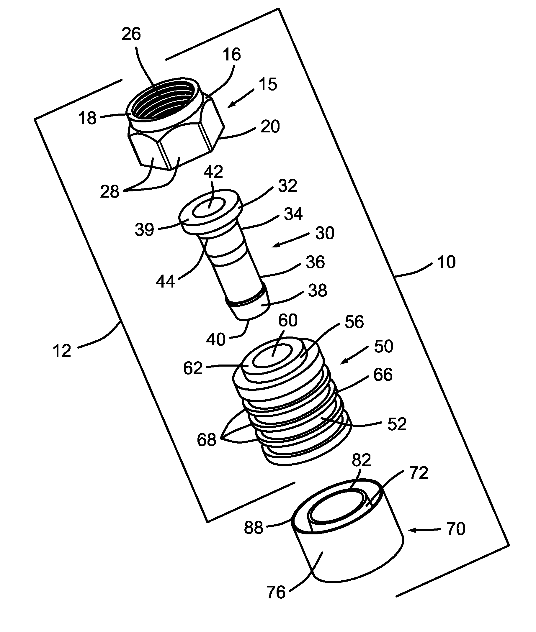
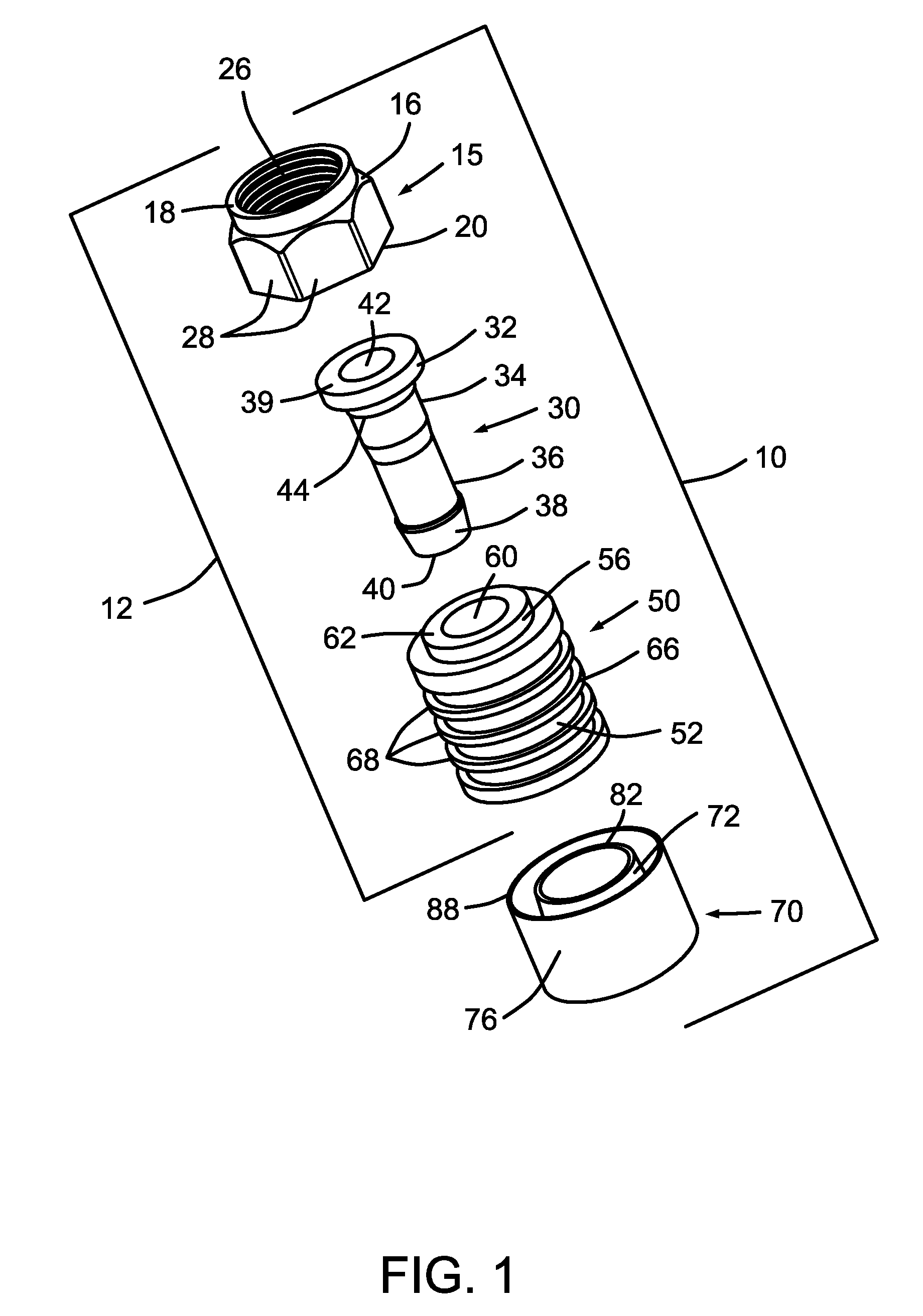
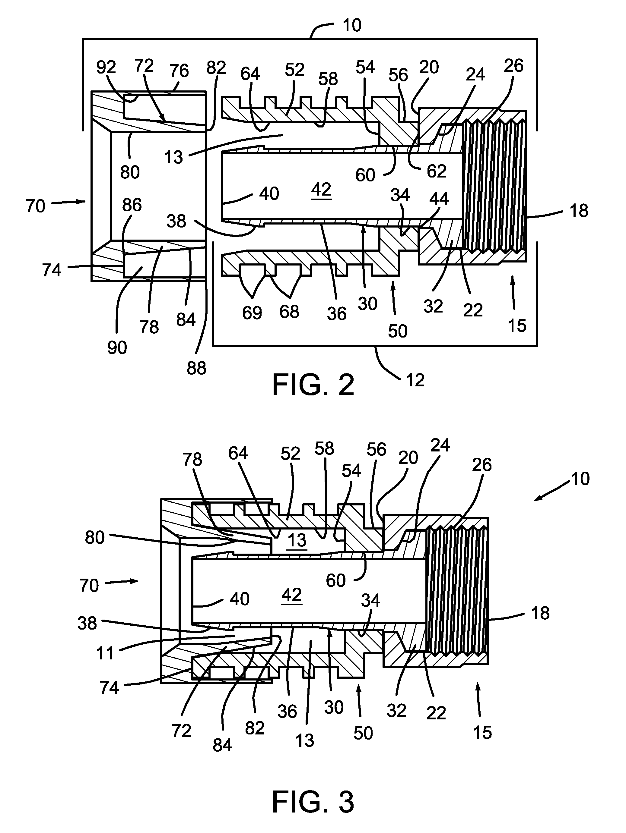
[0037]Referring first to FIGS. 1-3, coaxial cable connector 10 is comprised of a connector subassembly 12 and a compression cap 70. The connector subassembly 12 is of simple inexpensive construction, and may function a stand-alone crimpable cable connector, wherein the prepared end of a coaxial cable is secured within the subassembly 12 by crimping. Alternatively, the compression cap 70 may be placed over the end of a coaxial cable, and compressed onto the connector subassembly 12 to secure a prepared end of the cable within the compressed and assembled connector 10.

[0038]The connector subassembly 12 is comprised of a fastener 15, a tubular post 30, and a connector body 50. The fastener 15 is comprised of a body 16 having forward end 18 and a rearward end 20. The body 16 includes an axial bore 22 passing therethrough and having a shoulder 24 proximate to the rearward end 20. The fastener 15 is preferably a nut-type fastener. A portion of the axial bore 22 of the fastener 15 proximat...


PUM

PropertyMeasurementUnit
lengthaaaaaaaaaa
thicknessaaaaaaaaaa
sizesaaaaaaaaaa

Abstract

A coaxial cable connector for connecting a coaxial cable to an RF port, wherein the cable connector is comprised of a connector subassembly and a compression cap. The connector subassembly is of simple inexpensive construction and is comprised of a fastener, a tubular post, and a connector body. The connector subassembly may function a stand-alone crimpable cable connector. The compression cap may be placed over the end of a coaxial cable, and compressed onto the connector subassembly to secure a prepared end of the cable within the compressed and assembled connector.

Description

BACKGROUND OF THE INVENTION[0001]1. Field of the Invention[0002]The present invention relates generally to coaxial cable end connectors of the type employed in the cable television industry. More particularly, the present invention relates to an inexpensive connector that can be securely fitted to coaxial cables of several different sizes.[0003]2. Description of Related Art[0004]A conventional coaxial cable typically is comprised of a centrally located inner electrical conductor surrounded by and spaced inwardly from an outer cylindrical electrical conductor. The inner and outer conductors are separated by a dielectric insulating sleeve, and the outer conductor is encased within a protective dielectric jacket. The outer conductor can comprise a sheath of fine braided metallic strands, a metallic foil, or multiple layer combinations of either or both.[0005]In the transmission of cable television signals, a large low-loss high capacity coaxial cable is run between utility poles or bur...

Claims


Application Information

Patent Timeline
Patent Type & Authority Applications(United States)
IPC IPC(8): H01R9/05H01R43/20
CPCY10T29/53209H01R9/0524
Inventor SKEELS, STEPHEN J.MONTENA, NOAH
Owner PPC BROADBAND INC
Why Eureka
Try Eureka