Distributed hole recovery process using connectivity information

a technology of connectivity information and recovery process, applied in the field of coverage hole detection, can solve the problems of difficult to relax energy supply constraints, and often dynamic topology, so as to avoid single point failure and avoid high computational and storage capacity requirements

Inactive Publication Date: 2010-10-14
LI XIAOYUN +1
View PDF4 Cites 25 Cited by
  • Summary
  • Abstract
  • Description
  • Claims
  • Application Information

AI Technical Summary

Benefits of technology

[0015]The second objective of the invention is that the hole recovery process is distributed without any central controller, for the purpose of reliability and flexibility, and to avoid single point failure. It should also avoid making high requirements of computational and storage capacities for any node, and should not require any additional location equipment in resource constrained sensor networks.

Problems solved by technology

Furthermore, the topology is often dynamic, both due to node failure, and due to physical movement of nodes.
Low-cost deployment is one of the key objectives of wireless sensor networks, which together with the requirement for miniature sensor nodes with limited battery power implies that the resources available to individual nodes are severely limited.
In particular, constraints on energy supply are unlikely to be relaxed in the foreseeable future, furthermore, sensor nodes are usually unattended and are often inaccessible to human operators.
However, tiny sensor nodes are prone to accidental failure; one can fail either because it is operating in a harsh environment, or simply because it has run out of energy.
Also, it is unlikely that very small resource-constrained nodes can determine their location accurately through technologies such as GPS, particularly in a large WSN.
An algebraic topological method based upon homology theory which can detect coverage holes in a WSN without coordinates has been proposed by De Silva, Ghrist, R. and Muhammad, A. It employs a centralized control algorithm that requires connectivity information about all nodes in the sensing area, but cannot guarantee to detect the boundary of a hole accurately.
This algorithm does not require node coordinates to be known, but the node density must be high enough to guarantee sufficient accuracy, which is not suitable for randomly deployed sensor networks, because the node density of the area adjacent to a hole is often lower than that of a hole-free area.
Also, this algorithm cannot detect multiple adjacent holes.
Another problem is the high communication overhead due to frequent flooding, which takes place when the network topology changes due to node failure or node mobility.
These algorithms partition the target area into fixed hexagonal cells, and assume that a cell is covered if at least one node lies inside it, hence they generally cannot maintain full coverage (which is critical for WSN operation) without redundancy.

Method used


Image

  • Distributed hole recovery process using connectivity information
  • Distributed hole recovery process using connectivity information
  • Distributed hole recovery process using connectivity information

Examples


Embodiment Construction

A. Detailed Steps for the Invention

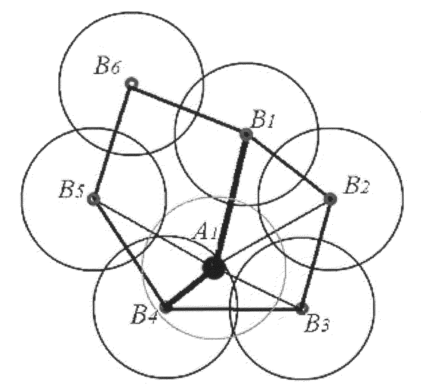
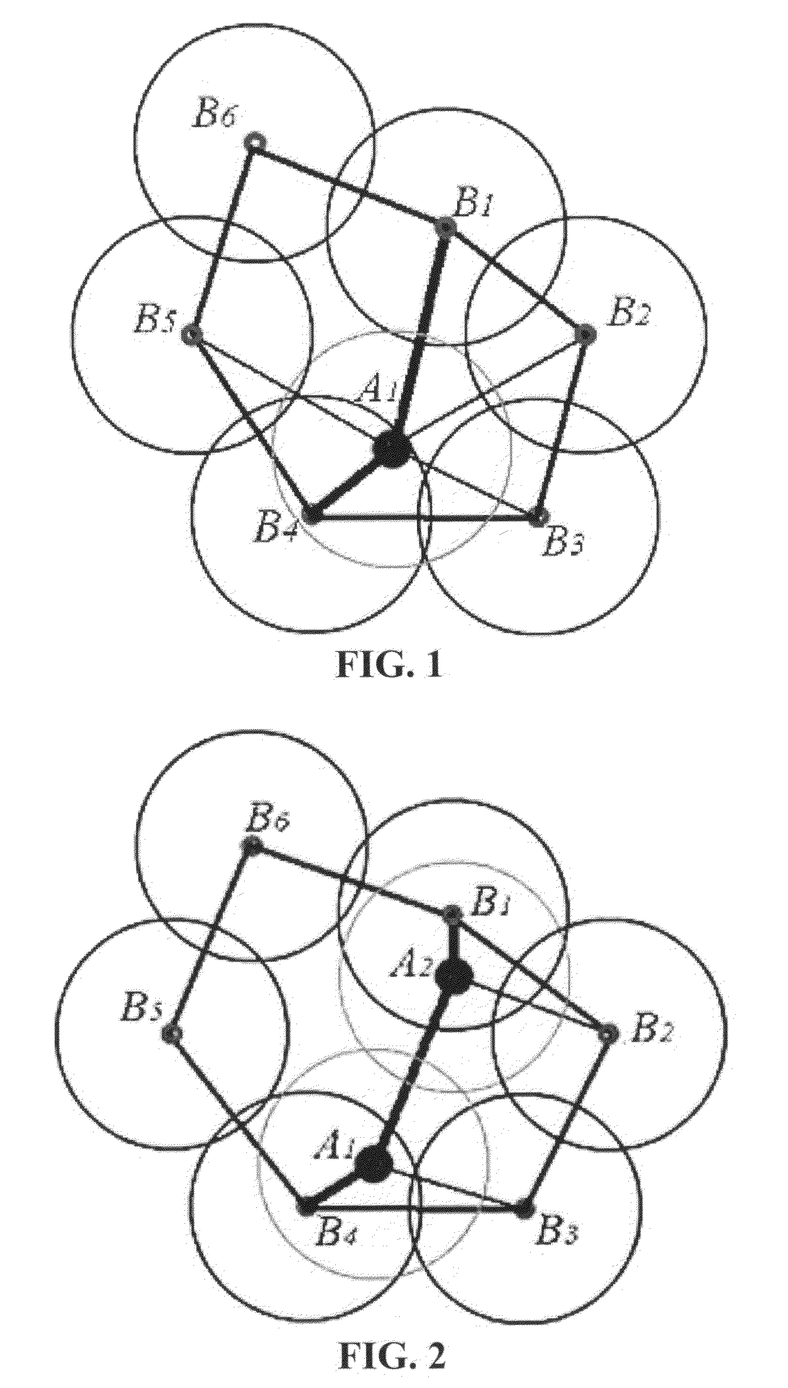
[0031]When a hole is detected as being enclosed by a polygon with N edges where N>3, (with each edge being a link between two adjacent active boundary nodes), each of the N boundary nodes has and only has links to two neighboring nodes among the other N−1 boundary nodes, and has no links to the other N−3 boundary nodes. FIG. 1. shows an example of a hole enclosed by a polygon with 6 edges defined by 6 adjacent active boundary nodes {B1 B2 B3 B4 B5 B6}.

[0032]Assume that each node has been allocated a node ID, and becomes aware of the IDs of its neighbors, by the end of the initial phase of setting up the network. When running the distributed hole recovery algorithm, each of the N boundary nodes adjacent to a detected hole only has to transmit a message to the others once or twice at most during each hole recovery iteration. Therefore each can be allocated a timeslot in advance at the following distributed hole recovery step 1 in order to avoid conte...


PUM


Abstract

A distributed coverage hole recovery process using connectivity information is proposed for wireless sensor networks and other wireless networks. A link is said to exist between two nodes which are sufficiently close. After a un-triangulated hole is detected enclosing by links between N (N>3) active boundary nodes, the distributed hole recovery process activates one or two redundant nodes to recover the hole at each iteration. This process is performed iteratively by each of the active boundary nodes adjacent to the hole independently without any central controller. It requires 2 hops connectivity or neighbor information from each boundary node adjacent to the hole. After each hole recovery iteration, the hole is reduced in size or split into two smaller holes. Then the hole recovery process repeats until the hole is recovered or detected as unrecoverable.

Description

CROSS-REFERENCE TO RELATED APPLICATIONS[0001]Not applicableSTATEMENT REGARDING FEDERALLY SPONSORED RESEARCH OR DEVELOPMENT[0002]Not applicableREFERENCE TO SEQUENCE LISTING, A TABLE, OR A COMPUTER PROGRAM LISTING COMPACT DISC APPENDIX[0003]Not applicableBACKGROUND OF THE INVENTION[0004]1. Field of the Invention[0005]The present invention relates to coverage hole detection in wireless sensor networks and other wireless networks.[0006]2. Description of the Related Art[0007]Wireless sensor networks (WSNs) have been widely researched as a technology for gathering sensed information such as temperature, pressure, humidity and vibration over a wide area and collecting it at one centralized point for storage and analysis. Such wireless sensor networks often cover a wide area, consisting of a very large number of nodes which may be densely deployed. Furthermore, the topology is often dynamic, both due to node failure, and due to physical movement of nodes. Low-cost deployment is one of the k...

Claims


Application Information

Patent Timeline
Patent Type & Authority Applications(United States)
IPC IPC(8): H04B7/00
CPCH04W84/18H04W24/04
Inventor LI, XIAOYUNHUNTER, DAVID KENNEDY
Owner LI XIAOYUN
Why Eureka
Try Eureka