Control device and control method for lockup clutch and engine torque in a vehicle

a control device and clutch technology, applied in the direction of gearing, fluid couplings, instruments, etc., can solve the problems of hydraulic fluid overheating, friction material generating a large amount of heat, and the difference between the engine speed and the turbine speed of the torque converter, so as to reduce the size suppress the excessive heating of the friction material of the lock-up clutch

Active Publication Date: 2010-10-14
TOYOTA JIDOSHA KK
View PDF12 Cites 12 Cited by
  • Summary
  • Abstract
  • Description
  • Claims
  • Application Information

AI Technical Summary

Benefits of technology

[0022]In this way, after the rotational speed difference (Ne−Nt) between the engine speed Ne and the turbine speed Nt is reduced, the lock-up clutch is engaged. Thus, [“excessive”?] heating of the friction material of the lock-up clutch may be suppressed. By so doing, durability of the friction material may be ensured without increasing the heat capacity of the friction material of the lock-up clutch. As a result, the size of the lock-up clutch may be reduced. Note that when the rotational speed difference (Ne−Nt) at the time when the lock-up ON condition is satisfied is smaller than or equal to the target rotational speed difference, durability of the friction material may be ensured even when the lock-up clutch is engaged. Thus, the lock-up clutch is immediately engaged.
[0028]In the above control device and control method, when the upper limit rotational speed difference is set in consideration of, for example, a heating value due to shearing of hydraulic fluid) of the torque converter and cooling ability of the vehicle, it is possible to prevent hydraulic fluid of the torque converter from overheating.
[0030]According to the aspects of the invention, when it is determined that the lock-up ON condition is satisfied, if the rotational speed difference between the engine speed Ne and the turbine speed Nt is large, the torque reduction control for the engine is executed, and the lock-up clutch is engaged after the rotational speed difference has been reduced to the target rotational speed difference. Thus, excessive heating of the friction material of the lock-up clutch may be suppressed and, as a result, the size of the lock-up clutch may be reduced.

Problems solved by technology

In particular, when power input from the engine is large, rotational speed the difference between the engine speed and the turbine speed of the torque converter increases and, therefore, the friction material generates a large amount of heat when the lock-up clutch engages.
When the above large rotational speed difference continues for a relatively long period of time, hydraulic fluid (automatic transmission fluid (ATF)) in the torque converter heats up due to agitation and finally the hydraulic fluid overheats.
Thus, the technologies described in JP-A-2004-263875 and JP-A-3-182648, provides no solution for the above problem.

Method used


Image

  • Control device and control method for lockup clutch and engine torque in a vehicle
  • Control device and control method for lockup clutch and engine torque in a vehicle
  • Control device and control method for lockup clutch and engine torque in a vehicle

Examples


Embodiment Construction

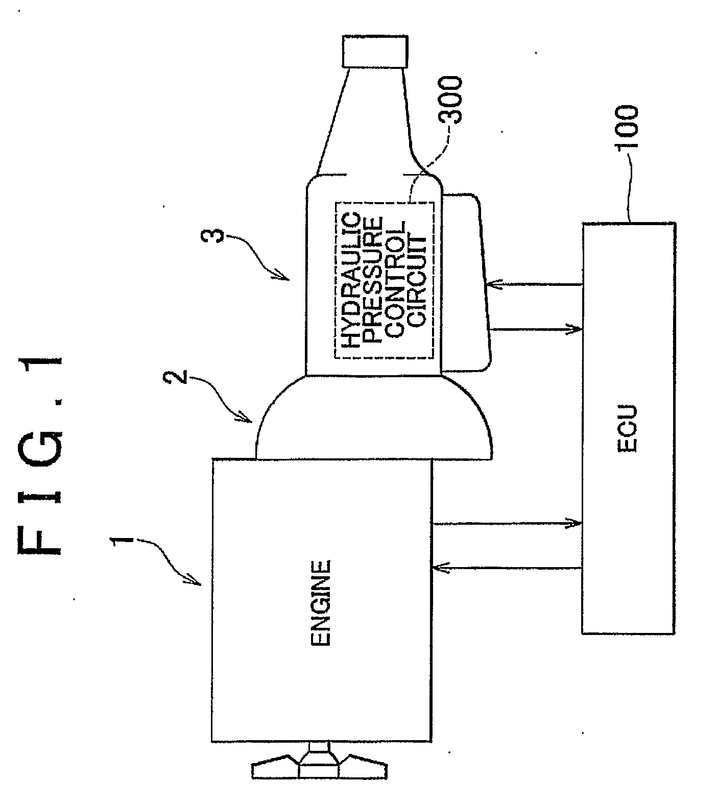
[0044]FIG. 1 is a schematic configuration diagram that shows a portion of a vehicle according to an embodiment of the invention. The vehicle of this example is an front-engine, rear-wheel-drive (FR) vehicle that includes an engine 1; a torque converter 2; an automatic transmission 3; an ECU 100; and the like. A control device and control method for a vehicle according to the aspects of the invention may be implemented by a program that is executed by the ECU 100. The engine 1, torque converter 2, automatic transmission 3 and various units of the ECU 100 will be described below.

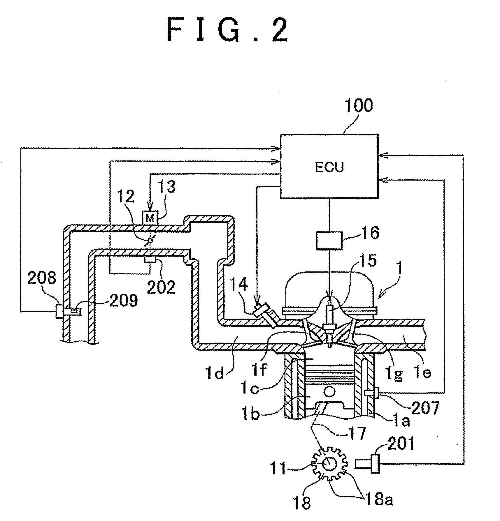
[0045]The engine 1 may be, for example, a four-cylinder gasoline engine. A cylinder block 1a, in which the cylinders are formed, accommodates pistons 1b, as shown in FIG. 2. The pistons 1b reciprocally move vertically. The pistons 1b are coupled through a connecting rod 17 to a crankshaft 11. The reciprocation of the pistons 1b is converted by the connecting rod 17 into rotation of the crankshaft 11. The crank...


PUM


Abstract

If the a rotational speed difference (Ne−Nt) between an engine speed (Ne) and a turbine speed (Nt) when it is determined that a lock-up ON condition (OFF→ON) is satisfied is large, the lock-up clutch is not engaged but torque reduction control is executed to reduce the engine speed (Ne), thus reducing the rotational speed difference (Ne−Nt) (steps ST13 and ST14). Then, once the rotational speed difference (Ne−Nt) has been reduced to the target rotational speed difference (Nslp), the lock-up clutch is engaged (steps ST15 and ST16). In this manner, excessive heating of the friction material of the lock-up clutch is suppressed which increases the longevity of the friction material.

Description

BACKGROUND OF THE INVENTION[0001]1. Field of the Invention[0002]The present invention relates to a control device and control method for a vehicle in which an engine (internal combustion engine) and an automatic transmission are installed and, more particularly, to a control device and control method for a vehicle equipped with a torque converter having a lock-up clutch and an automatic transmission.[0003]2. Description of the Related Art[0004]In a vehicle having an engine, a transmission transmits torque and rotational speed, generated by the engine, to driving wheels in accordance with vehicle running states. The transmission includes an automatic transmission that automatically and optimally sets a gear ratio between the engine and the driving wheels.[0005]The automatic transmission installed in a vehicle may be, for example, a planetary gear transmission that uses frictional engagement elements, such as clutches and brakes, and a planetary gear set to set a gear, and a belt-type...

Claims


Application Information

Patent Timeline
Patent Type & Authority Applications(United States)
IPC IPC(8): B60W10/02B60W10/06F16H61/14F16H59/14F16H59/46F16H59/72F16H63/50
CPCB60W2710/024F16H59/72F16H61/143Y10T477/735F16H2059/467F16H2059/725F16H2061/145F16H63/50
Inventor MATSUNAGA, HITOSHIOSHIMA, KOJI
Owner TOYOTA JIDOSHA KK
Why Eureka
Try Eureka