
Motor-operated valve and refrigeration cycle using the same

a technology of motor-operated valves and refrigeration cycles, which is applied in the direction of process and machine control, lighting and heating apparatus, instruments, etc., can solve the problem of difficult to perform flow rate control at a high accuracy, and achieve the effect of improving control accuracy in the refrigeration cycle, reducing pressure loss, and increasing energy saving efficiency

Active Publication Date: 2010-10-21
FUJIKOKI CORP
View PDF23 Cites 17 Cited by
  • Summary
  • Abstract
  • Description
  • Claims
  • Application Information

AI Technical Summary

Benefits of technology

[0023]The present invention has been made in view of the above described circumstances, and has its object to provide a motor-operated valve which during a normal flow, can control the flow rate at a high accuracy, and during a reverse flow, can pass the fluid so as to suppress pressure loss as much as possible, and a refrigeration cycle using the same.
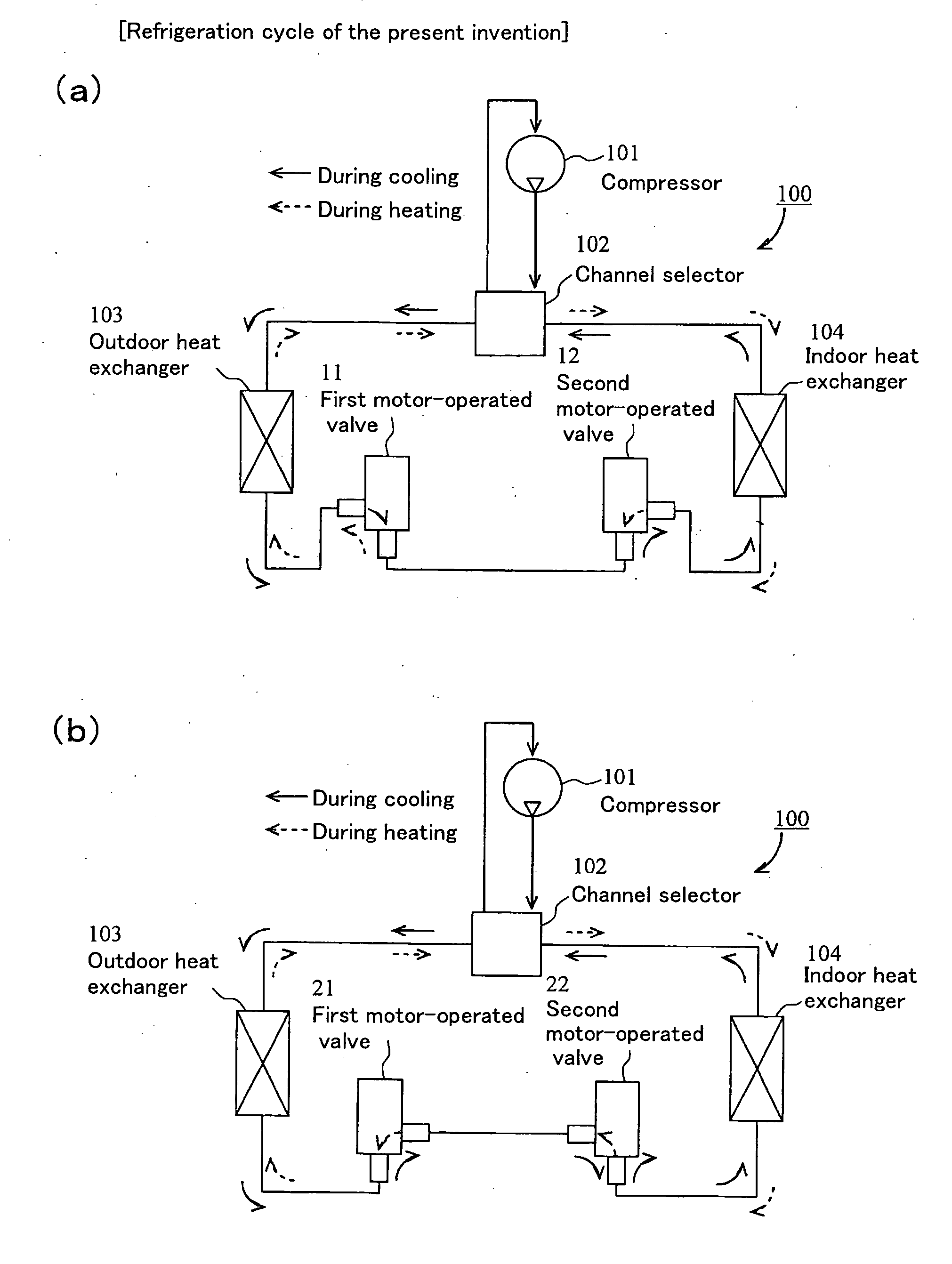
[0037]On the other hand, the refrigeration cycle relating to the present invention includes a compressor, a channel selector, an outdoor heat exchanger, and an indoor heat exchanger, in which a first expansion valve is disposed near the outdoor heat exchanger, and a second expansion valve is disposed near the indoor heat exchanger between the outdoor heat exchanger and the indoor heat exchanger; and is characterized in that the motor-operated valve is used as the first expansion valve and the second expansion valve, and when the refrigerant flows from the outdoor heat exchanger to the indoor heat exchanger, all or a majority of the refrigerant is made to flow without being passed through the orifice at the first expansion valve to decrease pressure loss as much as possible, and is made to flow only from between the main valve body and the orifice at the second expansion valve to perform flow rate control; when the refrigerant is made to flow from the indoor heat exchanger to the outdoor heat exchanger, all or a majority of the refrigerant is made to flow without being passed through the orifice at the second expansion valve to decrease pressure loss as much as possible, and the refrigerant is made to flow only from between the main valve body and the orifice at the first expansion valve to perform flow rate control.
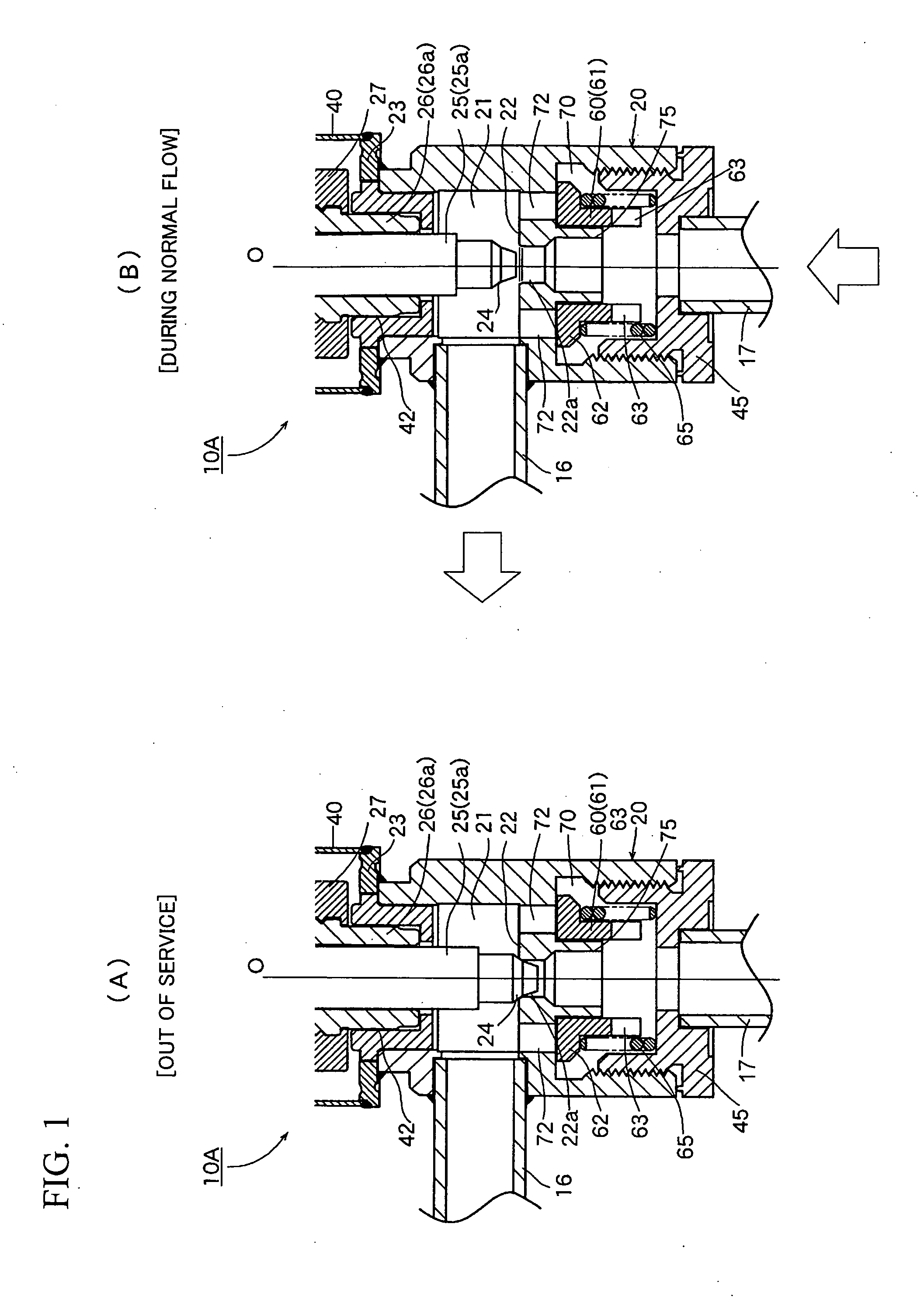
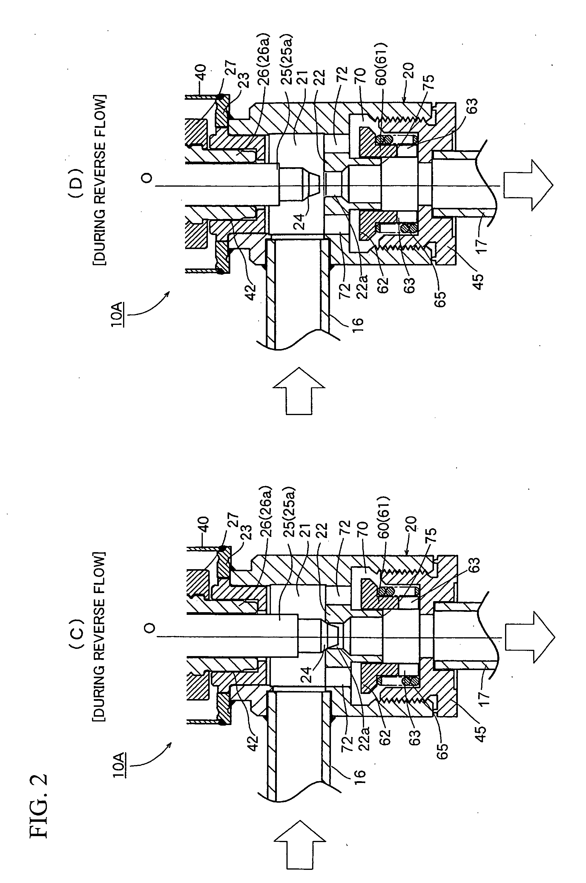
[0038]In a preferred mode of the motor-operated valve relating to the present invention, since a channel for bypassing the orifice which is opened / closed by the main valve body is formed, and a check valve body which closes the bypass channel during a normal flow, and opens it during a reverse flow is provided so that during a normal flow, the fluid is made to flow only from between the main valve body and the orifice, and during a reverse flow, all or a majority of the fluid is made to flow to the bypass channel without being passed through the orifice, it becomes possible to perform flow rate control at a high accuracy during a normal flow and to reduce pressure loss to the same level as that of a flow in a conduit during a reverse flow.
[0039]Therefore, by using the motor-operated valve relating to the present invention for a refrigeration cycle as an expansion valve, it is possible to significantly improve the control accuracy in refrigeration cycle and to reduce pressure loss as much as possible resulting in a significant increase in energy saving efficiency. Further, since there is no need of separately arranging and connecting a check valve for the piping as in conventional examples, it is possible to suppress man-hours and costs needed for piping to a low level.

Problems solved by technology

However, in such a proposed motor-operated valve, there is a problem that increasing the diameter of the orifice to decrease pressure loss will make it harder to perform flow rate control at a high accuracy.

Method used


Image

  • Motor-operated valve and refrigeration cycle using the same
  • Motor-operated valve and refrigeration cycle using the same
  • Motor-operated valve and refrigeration cycle using the same

Examples


Embodiment Construction

[0062]Hereafter, embodiments of the present invention will be described with reference to the drawings.

[0063]FIGS. 1(A) and 1(B), and FIGS. 2(A) and 2(B) are principal-part longitudinal sectional views of an embodiment (a first example) of the motor-operated valve relating to the present invention. Since the basic configuration of the motor-operated valve 10A of the shown example is substantially the same as that of the motor-operated valve 10′ of the above described conventional example shown in FIG. 9, portions corresponding to each part of the motor-operated valve 10′ of the conventional example shown in FIG. 9 is given the same reference characters to omit overlapping of description, and hereafter description will be made with emphasis placed on the valve main body 20 portion which is a principal part (characteristic portion).

[0064]The motor-operated valve 10A of the shown first example is configured such that during a normal flow as shown in FIG. 1(B), the refrigerant is made t...


PUM


Abstract

A motor-operated valve which can control the flow rate at a high accuracy during a normal flow, and can pass the fluid so as to suppress pressure loss as much as possible during a reverse flow, and a refrigeration cycle using the same are provided. It is configured such that during a normal flow, the fluid is made to flow only from between the main valve body 24 and the orifice 22 to perform flow rate control, and during a reverse flow, all or a majority of the fluid is made to flow to a bypass channel 70 without being passed through the orifice 22a to decrease pressure loss as much as possible. To be more specific, a check valve body 60 which closes the bypass channel 70 during a normal flow and opens it during a reverse flow is provided in the valve main body 20.

Description

BACKGROUND OF THE INVENTION[0001]1. Field of the Invention[0002]The present invention relates to motor-operated valves which are used by being incorporated in an air conditioning apparatus etc., and particularly to a motor-operated valve which is configured such that when the fluid (refrigerant) flows in a normal direction, the flow rate can be controlled at a high accuracy by adjusting the lift amount of a valve body, and when the fluid flows in a reverse direction, the pressure loss can be decreased as much as possible.[0003]2. Background Art[0004]FIG. 6 shows an example of the refrigeration cycle that is adopted in an air conditioning apparatus. This refrigeration cycle 100 includes two expansion valves, one of which is in general sufficient, for improving the energy saving efficiency etc., in addition to a compressor 101, a channel selector 102, an outdoor heat exchanger (condenser) 103, and an indoor heat exchanger (evaporator) 104 (a distributor and others are not shown). That...

Claims


Application Information

Patent Timeline
IPC IPC(8): G05D7/06F15B13/044F25B13/00
CPCF16K15/18F25B13/00Y02B30/72F25B2341/0653F25B2400/0411F25B41/062Y10T137/87563Y10T137/2584Y10T137/87555Y10T137/87507Y10T137/264Y10T137/87217Y02B30/70F25B41/35F25B41/325F25B41/38
Inventor SUGANUMA, TAKESHI
Owner FUJIKOKI CORP
Learn More