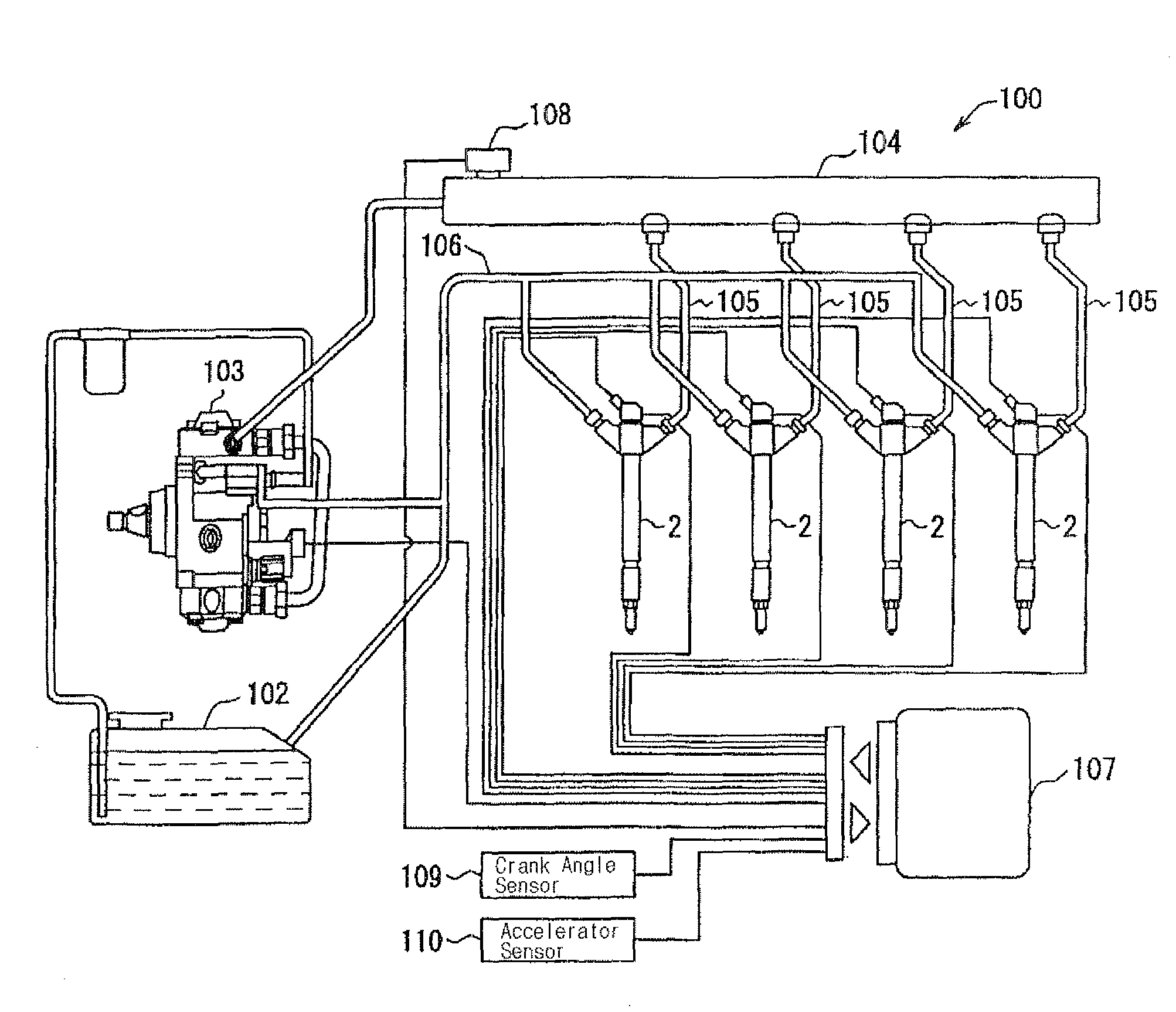
Fuel injection valve and fuel injection apparatus
a technology of fuel injection valve and fuel injection apparatus, which is applied in the direction of fuel injection apparatus, charge feed system, electric control, etc., can solve the problems of difficulty in accurately measuring the pressure of fuel, and achieve the effect of improving the accuracy of measuring the pressure and facilitating the machining of the diaphragm
- Summary
- Abstract
- Description
- Claims
- Application Information
AI Technical Summary
Benefits of technology
Problems solved by technology
Method used
Image

Examples
first embodiment
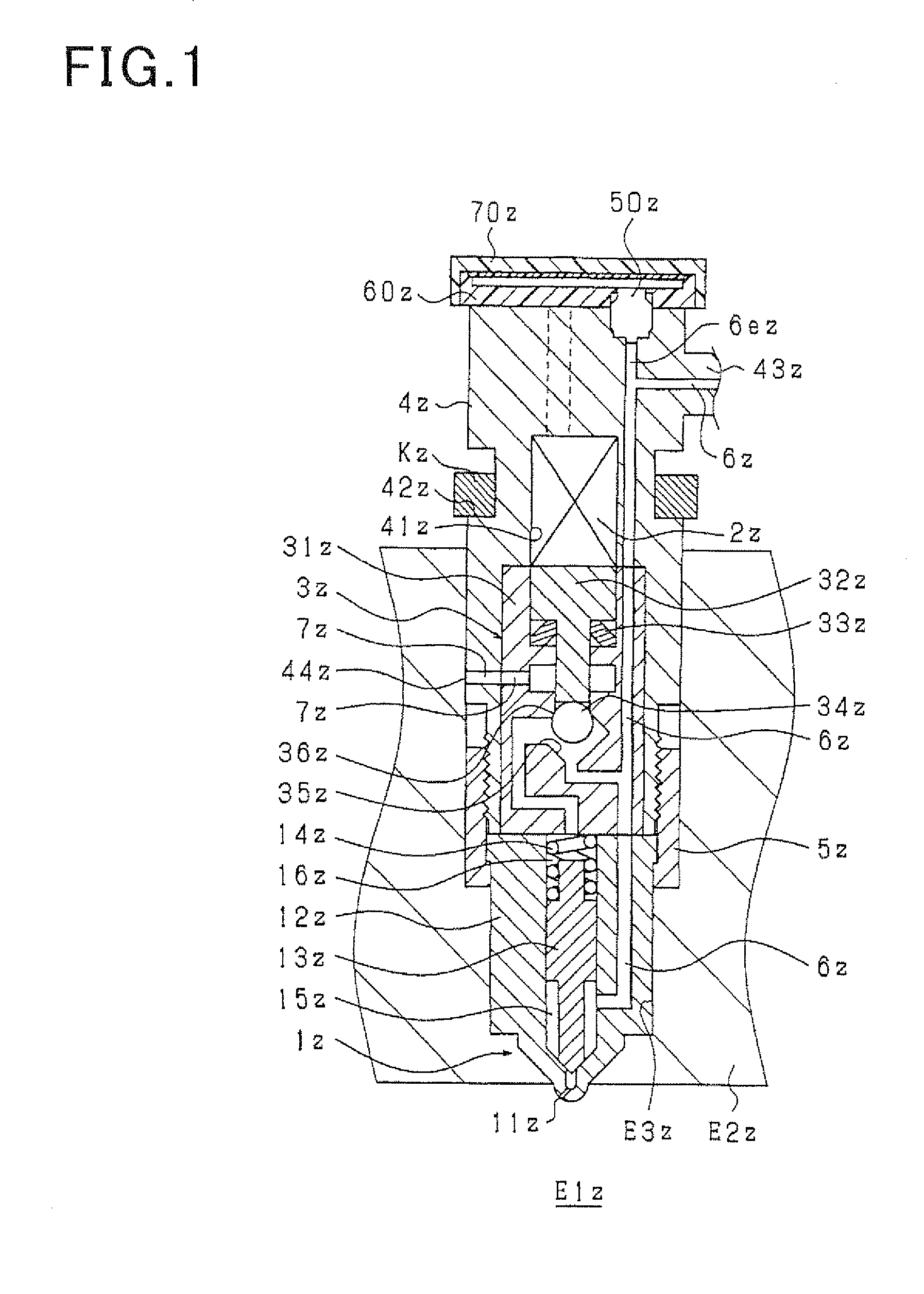
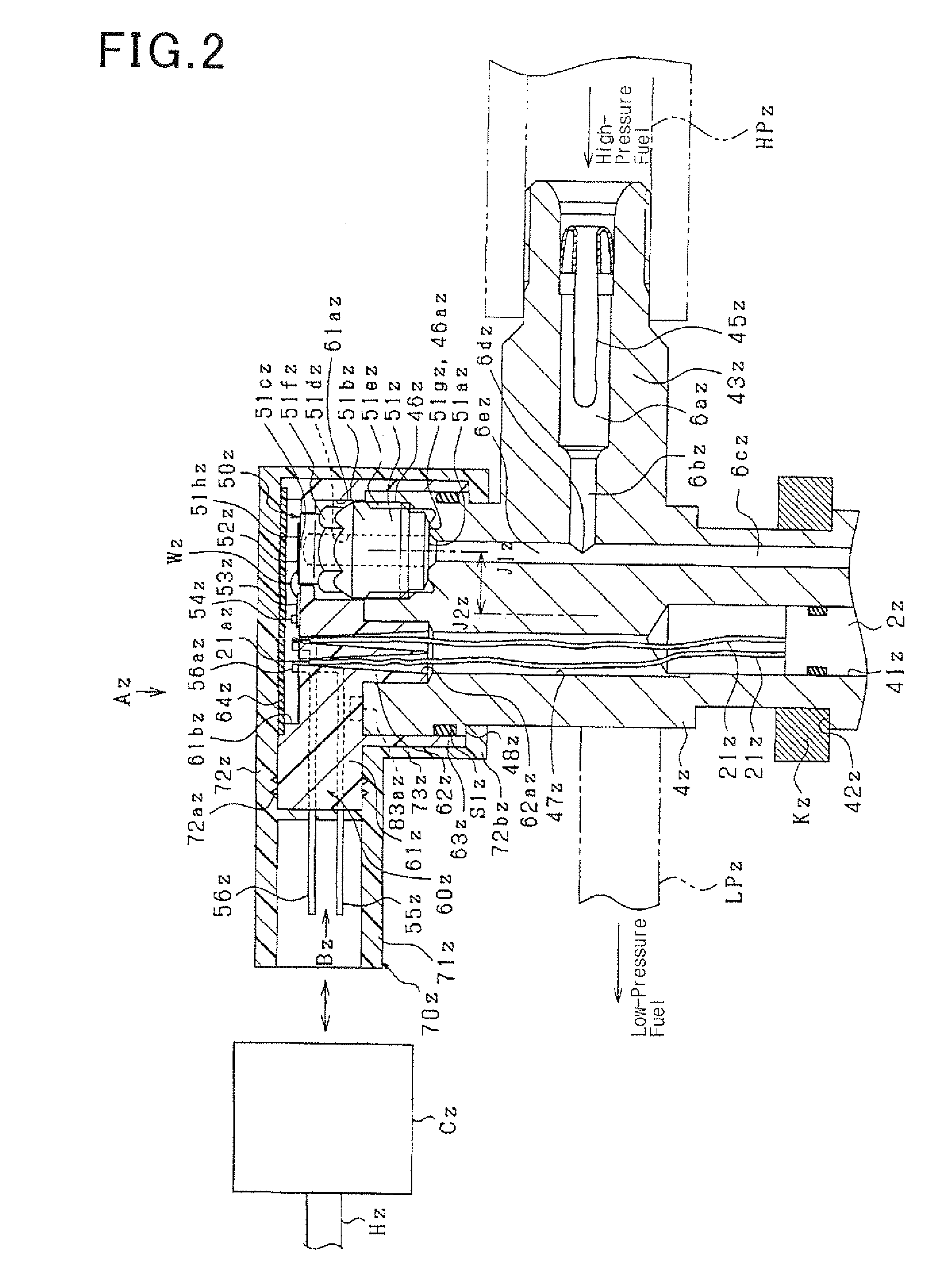
[0207]The first embodiment of the invention will be described using FIGS. 1 and 2. FIG. 1 is a schematic sectional view which shows an outline of inner structure of an injector (i.e., a fuel injection valve) according to this embodiment. FIG. 2 is an enlarged view for explaining FIG. 1 in detail.
[0208]First, a basic structure and operation of the injector will be described based on FIG. 1. The injector is to spray high-pressure fuel, as stored in a common rail (not shown), into a combustion chamber E1z formed in a cylinder of an internal combustion diesel engine and includes a nozzle 1z for spraying the fuel when the valve is opened, a piezo actuator 2z (opening / closing mechanism) which expands or contracts when charged or discharged electrically, and a back pressure control mechanism 3z (opening / closing mechanism) which is driven by the piezo actuator 2z to control the back pressure acting on the nozzle 1z.
[0209]The nozzle 1z is made up of a nozzle body 12z in which spray holes 11...
second embodiment
[0271]In this embodiment a memory chip Mz in which a correction value is stored to correct the pressure value, as measured by the fuel pressure sensors 50z is provided (see FIG. 5). Specifically, deviations between the pressure values, as measured by the strain gauge 52z, and actual pressures of the fuel are experimentally derived and stored as correction values in the memory chip Mz. A signal of the correction value is outputted to an external device such as the engine ECU. This enables the engine ECU to sample the correction value for the fuel pressure sensor 50z and correct the pressure value, as measured by the strain gauge 52z based on the correction value.
[0272]One of the three sensor terminals 55z, as used in the first embodiment, is employed as memory terminals 55z through which the correction value is outputted. Therefore, in addition to the drive terminals 56z, the sensor terminals 55z, and the ground terminal Gz, the memory terminals 55z are retained in the common connect...
third embodiment
[0274]The lead wires 21z of the piezo-actuator 2z and the fuel pressure sensor 50z are disposed inside the connector housing 70z. It is necessary to seal the lead wires 21z and the fuel pressure sensor 50z externally. This sealing structure of the first embodiment is so designed that the O-ring S1z (i.e., a sealing member) is interposed between the inner peripheral surface of the cylinder 63z of the molded resin 60z and the outer peripheral surface of the body 4z. Specifically, the single O-ring S1z seals both the lead wires 21z and the fuel pressure sensor 50z hermetically.
[0275]In contrast to this, the embodiment, as illustrated in FIG. 6, is designed to have O-rings S2z and S3z (i.e., sealing members) for the lead wires 21z and the fuel pressure sensor 50z. Specifically, the O-ring S2z is interposed between the cylinder body 51bz of the fuel pressure sensor 50z and the recess 46z of the molded resin 60z. The O-ring S3z is interposed between the lead wire hole 47z of the injector ...
PUM
 Abstract
Description
Claims
Application Information