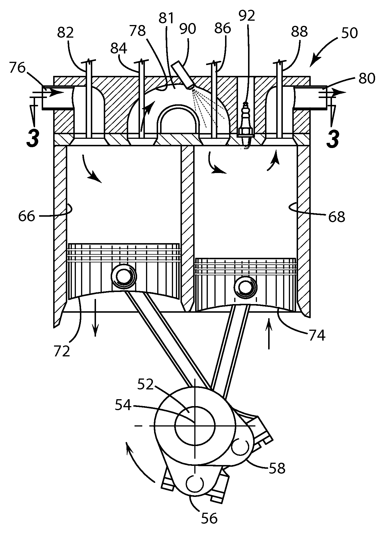
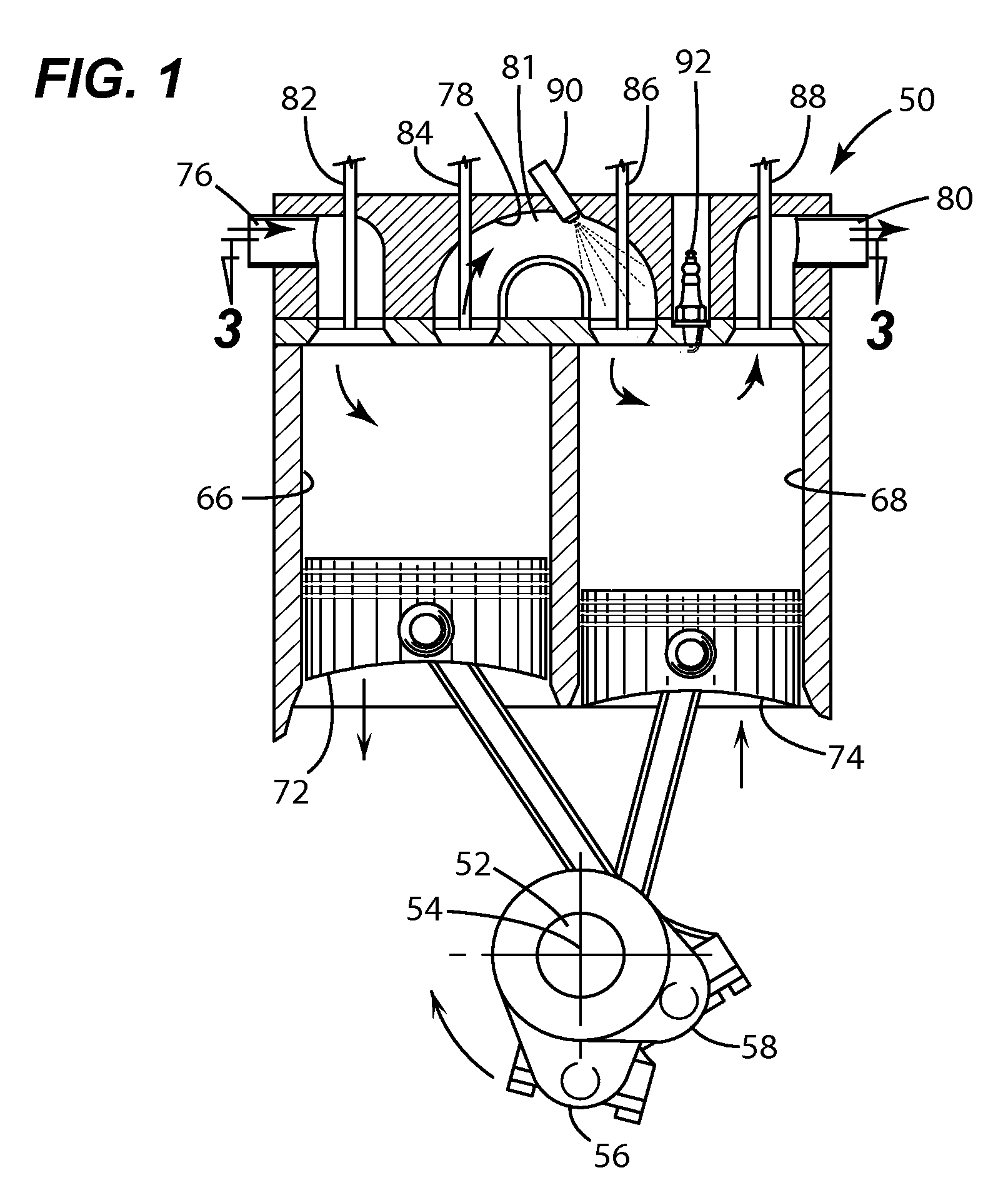
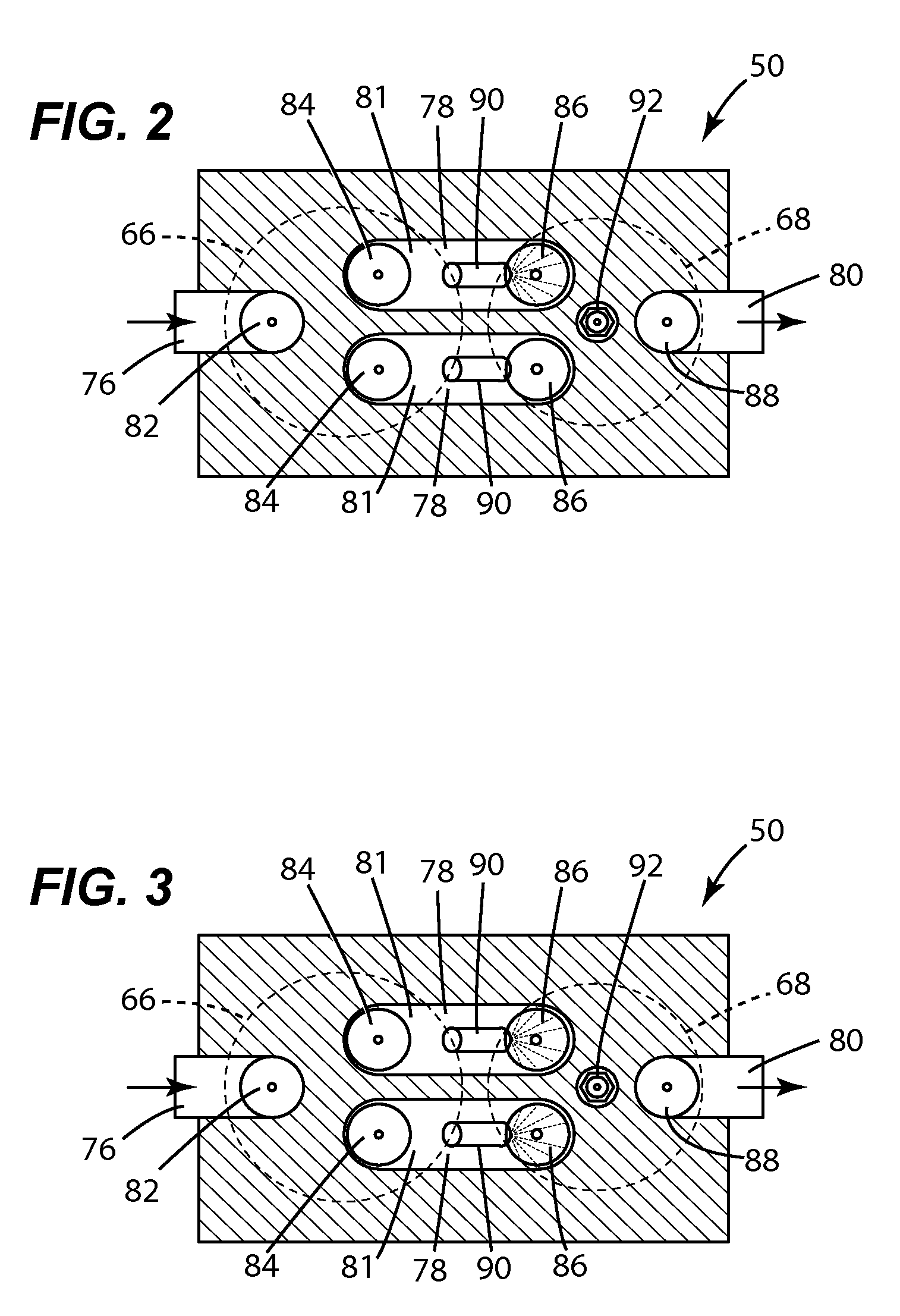
[0021]These and other advantages may be accomplished in a further embodiment of the present invention by providing an engine, comprising a crankshaft rotatable about a crankshaft axis, a compression piston slidably received within a compression cylinder and operatively connected to the crankshaft such that the compression piston is operable to reciprocate through an intake stroke and a compression stroke during a single rotation of the crankshaft, an expansion (power) piston slidably received within an expansion cylinder and operatively connected to the crankshaft such that the expansion piston is operable to reciprocate through an expansion stroke and an exhaust stroke during a single rotation of the crankshaft, at least two crossover passages interconnecting the compression and expansion cylinders, each of the at least two crossover passages including a crossover compression (XovrC) valve and a crossover expansion (XovrE) valve operable to define a pressure chamber therebetween, and at least two fuel injectors, each fuel injector corresponding to one of the at least two crossover passages, each fuel injector operable to add fuel to the exit end of the corresponding crossover passage, wherein the engine is operable to add fuel to the exit end of at least one but less than all of the at least two crossover passages during a single rotation of the crankshaft.
[0022]Optionally, in these three embodiments the expansion cylinder may be operable to receive fluid from at least one but less than all of the at least two crossover passages during a single rotation of the crankshaft. The compression cylinder may be operable to intake a charge of air and compress the charge into at least one but less than all of the at least two crossover passages during a single rotation of the crankshaft. The volume of a first of the at least two crossover passages may be between 40 and 60 percent of the volume of a second of the at least two crossover passages. The engine may be configured such that the pressure of the charge in the compression cylinder is less than 1 atmosphere when the compression piston is at its bottom dead center position.
[0023]These and other advantages may be accomplished in a further embodiment of the present invention by providing a method for controlling an engine at part-load, the engine including a crankshaft operable to rotate about a crankshaft axis of the engine, a compression piston slidably received within a compression cylinder and operatively connected to the crankshaft such that the compression piston is operable to reciprocate through an intake stroke and a compression stroke during a single rotation of the crankshaft, an expansion (power) piston slidably received within an expansion cylinder and operatively connected to the crankshaft such that the expansion piston is operable to reciprocate through an expansion stroke and an exhaust stroke during a single rotation of the crankshaft, and at least two crossover passages interconnecting the compression and expansion cylinders, each of the at least two crossover passages including a crossover compression (XovrC) valve and a crossover expansion (XovrE) valve operable to define a pressure chamber therebetween, the method comprising actuating at least one but less than all of the crossover compression (XorvC) valves during a single rotation of the crankshaft.
[0024]These and other advantages may be accomplished in a further embodiment of the present invention by providing a method for controlling an engine at part-load, the engine including a crankshaft operable to rotate about a crankshaft axis of the engine, a compression piston slidably received within a compression cylinder and operatively connected to the crankshaft such that the compression piston is operable to reciprocate through an intake stroke and a compression stroke during a single rotation of the crankshaft, an expansion (power) piston slidably received within an expansion cylinder and operatively connected to the crankshaft such that the expansion piston is operable to reciprocate through an expansion stroke and an exhaust stroke during a single rotation of the crankshaft, and at least two crossover passages interconnecting the compression and expansion cylinders, each of the at least two crossover passages including a crossover compression (XovrC) valve and a crossover expansion (XovrE) valve operable to define a pressure chamber therebetween, the method comprising actuating at least one but less than all of the crossover expansion (XovrE) valves during a single rotation of the crankshaft.
[0025]These and other advantages may be accomplished in a further embodiment of the present invention by providing a method for controlling an engine at part-load, the engine including a crankshaft operable to rotate about a crankshaft axis of the engine, a compression piston slidably received within a compression cylinder and operatively connected to the crankshaft such that the compression piston is operable to reciprocate through an intake stroke and a compression stroke during a single rotation of the crankshaft, an expansion (power) piston slidably received within an expansion cylinder and operatively connected to the crankshaft such that the expansion piston is operable to reciprocate through an expansion stroke and an exhaust stroke during a single rotation of the crankshaft, at least two crossover passages interconnecting the compression and expansion cylinders, each of the at least two crossover passages including a crossover compression (XovrC) valve and a crossover expansion (XovrE) valve operable to define a pressure chamber therebetween, and at least two fuel injectors, each fuel injector corresponding to one of the at least two crossover passages, each fuel injector operable to add fuel to the exit end of the corresponding crossover passage, the method comprising adding fuel to the exit end of at least one but less than all of the crossover passages during a single rotation of the crankshaft.
[0026]Optionally, in these three embodiments the method may further include the step of determining which of the fuel injectors to use to add the fuel based on at least one of the load and speed of the engine. The method may include the step of determining which of the crossover expansion (XovrE) valves to actuate based on at least one of the load and speed of the engine. The method may include the step of determining which of the crossover compression (XovrC) valves to actuate based on at least one of the load and speed of the engine. The volume of a first of the at least two crossover passages may be between 40 and 60 percent of the volume of a second of the at least two crossover passages. The engine may be configured such that the pressure of the charge in the compression cylinder is less than 1 atmosphere when the compression piston is at its bottom dead center position.

